Continue to Site

Welcome to EDAboard.com

Welcome to our site! EDAboard.com is an international Electronics Discussion Forum focused on EDA software, circuits, schematics, books, theory, papers, asic, pld, 8051, DSP, Network, RF, Analog Design, PCB, Service Manuals... and a whole lot more! To participate you need to register. Registration is free. Click here to register now.

Stability of the CSA amplifier

Status
Not open for further replies.
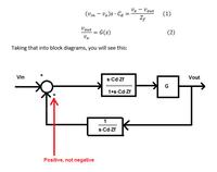
Yes I know. You need to refer to the exact G expression considering all circuit elements, as calculated above.


Thank you... But I really request you to show me once how to calculate AB (loop gain) manually, Please could you solve on a paper and send me with the pictures....Please...

- - - Updated - - -

Yes I know. You need to refer to the exact G expression considering all circuit elements, as calculated above.

That's what SapWin calculates for the CSA transfer function (closed loop gain). Please rewrite respectively.
Code:
v1:

+ (  - Hgm Cd Rf Ro + Cd Ro ) j w
- (  Cf Cd Rf Ro ) w^2
------------------------------------------------------------------------------
+ (  Hgm Ro +1 )
+ (  Cd Ro + Cd Rf + Hgm Cf Rf Ro + Cf Rf + Co Ro ) j w
- (  Cf Cd Rf Ro + Co Cd Rf Ro + Co Cf Rf Ro ) w^2

View attachment 136610


Thanks a lot... But as I said, I just need to study the stability of the circuit and for that I guess loop gain expression is sufficient. But really thank you for helping me.. Could you show me on a paper how to get loop gain expression. Please... This is the first time I am doing it...
Please.. If you can solve on a paper and send me pictures so that I can understand, just once..
 

Loop gain is the transfer function of a RC/C voltage divider with parallel RC load impedance, fed by a current source.

Output load Zo = Ro || (1/sCo)
Feedback Zf = Rf || (1/sCf)
Detector Zd = 1/sCd

loop gain = -gm*(Zo || Zf+Zd)*Zd/(Zf+Zd)

Should give the expression calculated by SapWin in post #17.


Thanks a lot... So this expression in post #17 is true in any case...i mean if Cout is nearly equal to cf also..
Can you please show me how to find "A" (open loop gain ) and B individually for this circuit...

Please show me once for this circuit such that I can do it for other circuits. I know It's like breaking the loop from the output and apply test signal. But please could you implement and make me explain for this circuit... A and B individually
Please...

- - - Updated - - -

Your circuit is a shunt shunt topology. In order to calculate open loop gain "A" , you have to actually break the feedback loop and calculate it like it is shown in the book of Sedra-Microelectronic circuits.

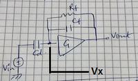
In this case, as you have calculated the transfer function of the cascode amplifier and it has infinite input impedance, then you can write equations like in an op amp and solve them. See attached picture.


- - - Updated - - -

Vx in the attached picture is show here:


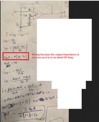
Please have once have a look on these pictures.. Please tell me if my approach is correct...
Please guide me give your esteem suggestions

https://obrazki.elektroda.pl/1397558500_1488451743.jpg
https://obrazki.elektroda.pl/2410967000_1488451746.jpg
 

Please have once have a look on these pictures.. Please tell me if my approach is correct...
R11 is wrong. R11 = Rf // Cf = Rf/(1+s*Cf*Rf)
I do not see where you have calculated R22. Anyway, R22 = R11 as I have showed above this line, not in your picture #1.

See here:


This is the beta circuit:
 

R11 is wrong. R11 = Rf // Cf = Rf/(1+s*Cf*Rf)
I do not see where you have calculated R22. Anyway, R22 = R11 as I have showed above this line, not in your picture #1.

See here:


This is the beta circuit:


Thanks a lot...I have calculated Beta.
Beta = ZD/ZD+ZF
Beta= RfsCf+1/Rfs(Cf+Cd)+1...

I guess, this expression is correct..??
 

Beta = ZD/ZD+ZF
I can not see any ZD in the feedback circuit.
BETA= -1/Zf

By the way, starting with the closed loop transfer function showed by FvM in post #20, the circuit can not be unstable under no matter what circumstances. See below.


I can not see any ZD in the feedback circuit.
BETA= -1/Zf

By the way, starting with the closed loop transfer function showed by FvM in post #20, the circuit can not be unstable under no matter what circumstances. See below.


Thank you... But for my actual circuit.. there is ZD... We apply test signal and current source will be open. By voltage divider we can find out Beta.
I have attached a picture below this..


https://obrazki.elektroda.pl/8129988200_1488477591.jpg

Please tell me if it is correct..
 

In post #24, the picture below the phrase "This is the beta circuit:" , are you talking about that circuit and replacing "If " with the current source in parallel with ZD ?

If not, please tell me how did you arrive to the circuit which you found Beta=ZD/ZD+ZF
 

In post #24, the picture below the phrase "This is the beta circuit:" , are you talking about that circuit and replacing "If " with the current source in parallel with ZD ?

If not, please tell me how did you arrive to the circuit which you found Beta=ZD/ZD+ZF


Please see the pictures. You think there won't be any effect of Cd in Beta(B) expression.

**broken link removed**.
https://obrazki.elektroda.pl/6444913700_1488482830.jpg

- - - Updated - - -

Please see the pictures. You think there won't be any effect of Cd in Beta(B) expression.

https://obrazki.elektroda.pl/9239114100_1488483247.jpg
https://obrazki.elektroda.pl/8150523900_1488483286.jpg
 

If you had followed the procedure already explained, you would have solved this simple exercise 10 times by now.


Thanks a lot...I have calculated Beta.
Beta = ZD/ZD+ZF
Beta= RfsCf+1/Rfs(Cf+Cd)+1...

I guess, this expression is correct..??


I am still thinking why there won't be any effect of Cd in Beta expression...??
According to for Charge senstive amplifier Beta= -1/Zf always..??

- - - Updated - - -

If you had followed the procedure already explained, you would have solved this simple exercise 10 times by now.


I am really sorry, I would like to apologize.. I have understood the diagram of shunt shunt config. from Sedra. and Smith book.

https://obrazki.elektroda.pl/7238713600_1488487340.jpg

If I calculate Vout/In, then that will be my "A" open loop gain... Please tell me...

- - - Updated - - -

If you had followed the procedure already explained, you would have solved this simple exercise 10 times by now.


I am really sorry, I am mixing things, # post no 31 is not correct.
Please tell me if this picture is correct...

If i calculate Vout/Iin for this circuit shown in picture below, that will be my open loop gain "A"

https://obrazki.elektroda.pl/1967434800_1488488028.jpg
 

The last picture is correct. Good job !:thumbsup:

Thanks a lot...But the issue is the equation is coming huge... How to deal with this....What should i understand with this equation. Calculation shown below..
And can I take loop gain equation from #post no 17 directly...???

Please see below..

https://obrazki.elektroda.pl/8462670200_1488531894.jpg
https://obrazki.elektroda.pl/9577571300_1488531929.jpg
https://obrazki.elektroda.pl/9408529300_1488532039.jpg
https://obrazki.elektroda.pl/6130514300_1488532128.jpg
 

Obviously yes. Post #22 along with the schematic on post #17 and the loop gain expression.

Thank you...
So in Post #22..
loop gain = -gm*(Zo || Zf+Zd)*Zd/(Zf+Zd)

From this equation how we can know what is A and B respectively...

Yesterday, as I calculated "A" open loop gain is not related to the expression mentioned above...Please let me know how we can find out A and B from the above loop gain expression..

- - - Updated - - -

Loop gain is the transfer function of a RC/C voltage divider with parallel RC load impedance, fed by a current source.

Output load Zo = Ro || (1/sCo)
Feedback Zf = Rf || (1/sCf)
Detector Zd = 1/sCd

loop gain = -gm*(Zo || Zf+Zd)*Zd/(Zf+Zd)

Should give the expression calculated by SapWin in post #17.


Please could you make me understand how you have written loop gain expression...
Please
 

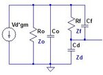
The transfer function of this equivalent circuit

csa lg circ.jpg
 
  • Like
Reactions: CataM

    CataM

    Points: 2
    Helpful Answer Positive Rating
Thanks...But from the post no # 17...how we can determine A and B expressions...

And also from that loop gain expression what do you understand...I mean i would like to study the stability... How to proceed...
 

I'm not completely sure about your definition of A and B. I presume, B means the feedback factor β, which is simply the transfer function of the voltage divider Zd/(Zd + Zf), as written in post #25 (+ necessary parenthesis).
 

I'm not completely sure about your definition of A and B. I presume, B means the feedback factor β, which is simply the transfer function of the voltage divider Zd/(Zd + Zf), as written in post #25 (+ necessary parenthesis).


"A" is the open loop gain and "B" is the feedback factor (β)...
From you expression , can we say...-gm*(Zo || Zf+Zd) is "A" is the open loop gain...???
 

Unfortunately the amplifier is rather an OTA than an OP and the calculated G is only correct for Co >> Cf, as mentioned. The exact transfer function is even more complex than the complete loop gain.

According to SapWin4

G = -gm*Ro*(1+(Cd+Cf)Rf s)/(1+(CdRo+CdRf+CfRf+CoRo)s + (CfCd+CoCd+CoCf)RfRo s²)

View attachment 136609

loop gain = -gm*Ro*(1+(CfRf s)/(1+(CdRo+CdRf+CfRf+CoRo)s + (CfCd+CoCd+CoCf)RfRo s²)


Thanks a lot for giving me this loop gain expression, but when I have finding out the roots of this equation, the roots are coming positive..I mean x=(-b±√(b^2-4ac))/2a.. b^2 is coming greater than 4ac term..What to do..??
 

Status
Not open for further replies.

Part and Inventory Search

Welcome to EDABoard.com

Sponsor

Back
Top