tisheebird
Member level 5
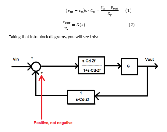
Yes I know. You need to refer to the exact G expression considering all circuit elements, as calculated above.
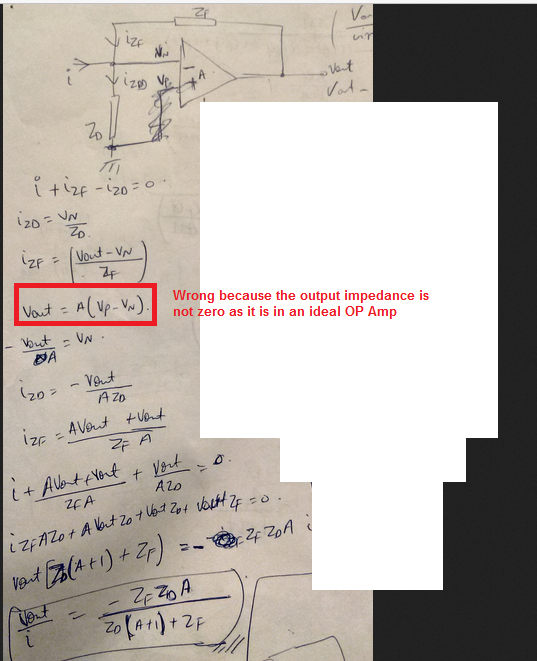
Thank you... But I really request you to show me once how to calculate AB (loop gain) manually, Please could you solve on a paper and send me with the pictures....Please...
- - - Updated - - -
Yes I know. You need to refer to the exact G expression considering all circuit elements, as calculated above.
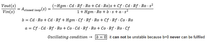
That's what SapWin calculates for the CSA transfer function (closed loop gain). Please rewrite respectively.
Code:v1: + ( - Hgm Cd Rf Ro + Cd Ro ) j w - ( Cf Cd Rf Ro ) w^2 ------------------------------------------------------------------------------ + ( Hgm Ro +1 ) + ( Cd Ro + Cd Rf + Hgm Cf Rf Ro + Cf Rf + Co Ro ) j w - ( Cf Cd Rf Ro + Co Cd Rf Ro + Co Cf Rf Ro ) w^2
View attachment 136610
Thanks a lot... But as I said, I just need to study the stability of the circuit and for that I guess loop gain expression is sufficient. But really thank you for helping me.. Could you show me on a paper how to get loop gain expression. Please... This is the first time I am doing it...
Please.. If you can solve on a paper and send me pictures so that I can understand, just once..