cupoftea
Advanced Member level 5
Hi,
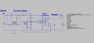
The attached (LTspice and PNG) is a bog standard linear regulator with vin = 20V, for a garment industry application.
Vout can be set anywhere from 0V to 16V.
Usually i(out) is 64mA max.
(Sometimes the load may source up to 100mA to the product, but this actually isnt an intended situation).
Sometimes the regulator is required to pulse the output on and off at 50% duty and T=10ms. (ie from 0V to the regulation voltage and back etc etc)
Do you believe the opamp, with the same shown compensation 47pF, would show good stability if the opamp
were changed for LM324, or LM358, TL074, TL084C, TL084H, OPA1679, MC33174, or LM2902? (ie, any cheap opamp)
....and when in the pulsed output operation, the rise and fall times would be within 50us of each other?
Noting that there is no load capacitance. (the rails of the opamp are 20V and -3v3)
LT1006
TL084C
TL084H
LM324
LM358
LM2902
TL074
OPA1679
MC33174
The attached (LTspice and PNG) is a bog standard linear regulator with vin = 20V, for a garment industry application.
Vout can be set anywhere from 0V to 16V.
Usually i(out) is 64mA max.
(Sometimes the load may source up to 100mA to the product, but this actually isnt an intended situation).
Sometimes the regulator is required to pulse the output on and off at 50% duty and T=10ms. (ie from 0V to the regulation voltage and back etc etc)
Do you believe the opamp, with the same shown compensation 47pF, would show good stability if the opamp
were changed for LM324, or LM358, TL074, TL084C, TL084H, OPA1679, MC33174, or LM2902? (ie, any cheap opamp)
....and when in the pulsed output operation, the rise and fall times would be within 50us of each other?
Noting that there is no load capacitance. (the rails of the opamp are 20V and -3v3)
LT1006
TL084C
TL084H
TL084H data sheet, product information and support | TI.com
TI’s TL084H is a Quad, 40-V, 5.25-MHz, 4-mV offset voltage, 20-V/µs, In to V+ op amp with -40°C to 125°C operation. Find parameters, ordering and quality information
www.ti.com
LM324
LM324 data sheet, product information and support | TI.com
TI’s LM324 is a Quad 30-V 1.2-MHz operational amplifier. Find parameters, ordering and quality information
www.ti.com
LM358
LM358 data sheet, product information and support | TI.com
TI’s LM358 is a Dual, 30-V, 700-kHz operational amplifier. Find parameters, ordering and quality information
www.ti.com
LM2902
LM2902 data sheet, product information and support | TI.com
TI’s LM2902 is a Quad, 26-V 1.2-MHz 2-mV offset voltage operational amplifier. Find parameters, ordering and quality information
www.ti.com
TL074
TL074 data sheet, product information and support | TI.com
TI’s TL074 is a Quad, 30-V, 3-MHz, high slew rate (13-V/µs), In to V+, JFET-input op amp. Find parameters, ordering and quality information
www.ti.com
OPA1679
OPA1679 data sheet, product information and support | TI.com
TI’s OPA1679 is a Low distortion (-120 dB), low noise (4.5nV/rtHz), quad audio op amp. Find parameters, ordering and quality information
www.ti.com
MC33174
Attachments
Last edited: