Continue to Site

Welcome to EDAboard.com

Welcome to our site! EDAboard.com is an international Electronics Discussion Forum focused on EDA software, circuits, schematics, books, theory, papers, asic, pld, 8051, DSP, Network, RF, Analog Design, PCB, Service Manuals... and a whole lot more! To participate you need to register. Registration is free. Click here to register now.

[SOLVED] Small footprint, 3V pk-pk, 7KHz, triangle signal generator

Status
Not open for further replies.

expert_vision

Junior Member level 3
Joined
Dec 5, 2012
Messages
26
Helped
3
Reputation
6
Reaction score
3
Trophy points
1,283
Activity points
1,506
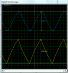
I designed a 3V pk-pk 7KHz triangle signal generator following the NE555 datasheet application, as shown in the picture below.
My only fear is though, that the signal might not look as good as in the simulation, considering that the op amp is at it's very edge operating at >7KHz with 100x (40dB) closed-loop gain.

Are there better ways to achieve such a signal?
The signal is used for PWM.
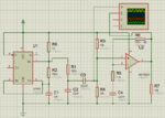
sch.PNGosc.PNG
 

Your "triangle wave" has curved sides because it is very simply produced by the capacitor being charged and discharged by a resistor.
If the circuit is an integrator with an opamp then the triangle wave will be almost perfect.
 

Many oscillators must be "kicked" to get them started in a simulator. In a real circuit the abrupt power supply voltage rise kicks them to get them started.
 

Status
Not open for further replies.

Similar threads

Part and Inventory Search

Welcome to EDABoard.com

Sponsor

Back
Top