naseerak
Full Member level 5
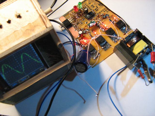
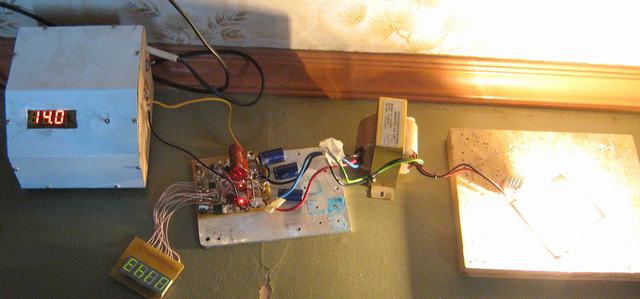
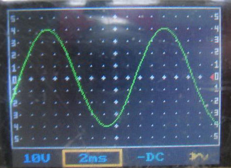
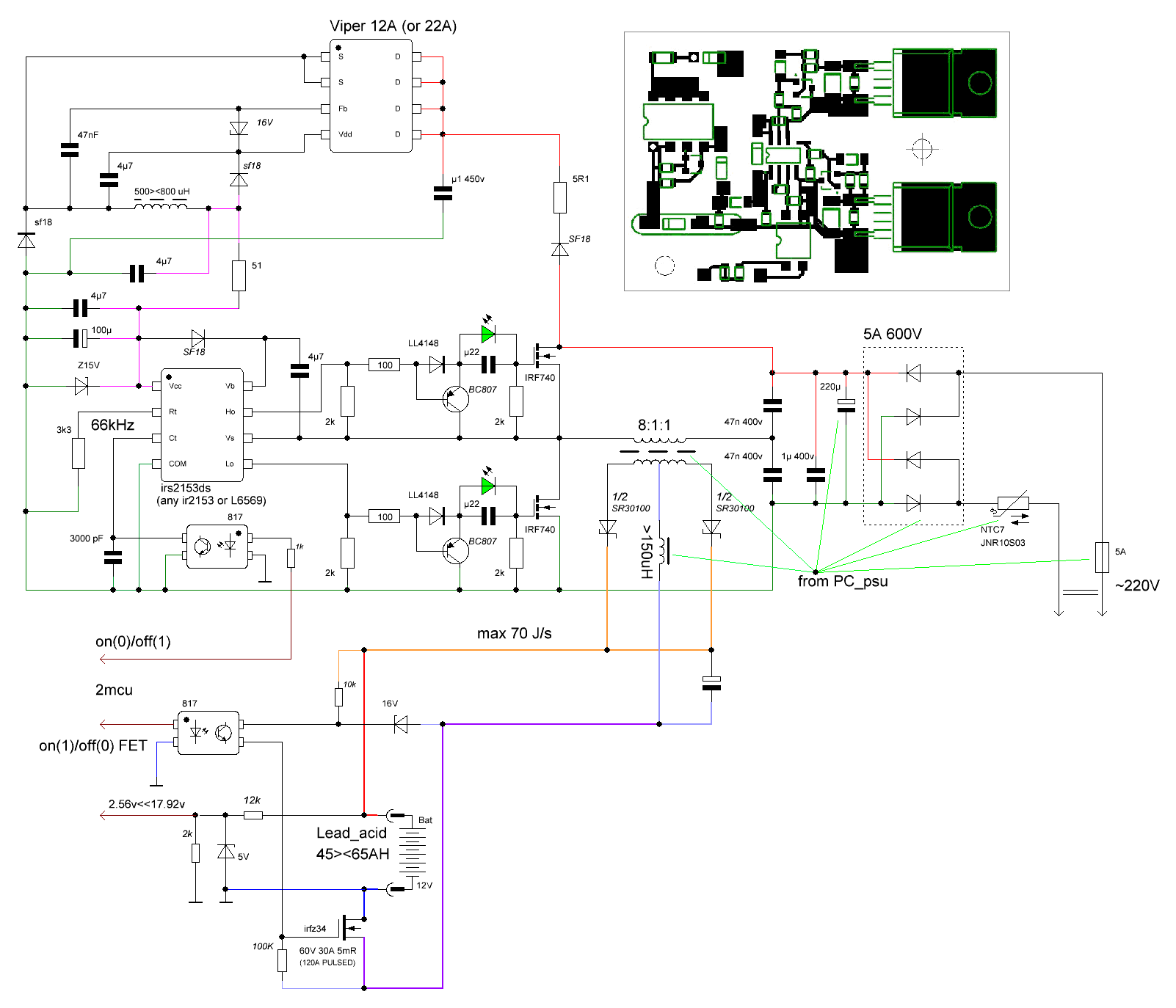
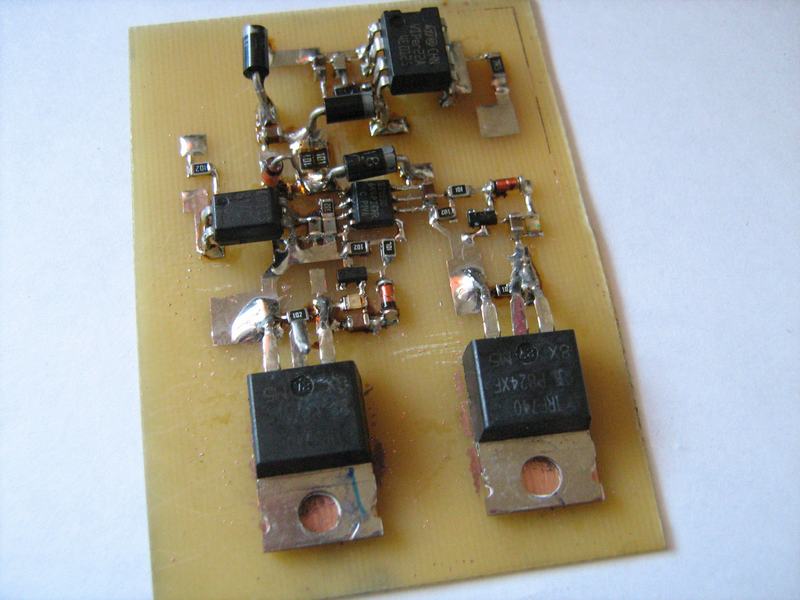
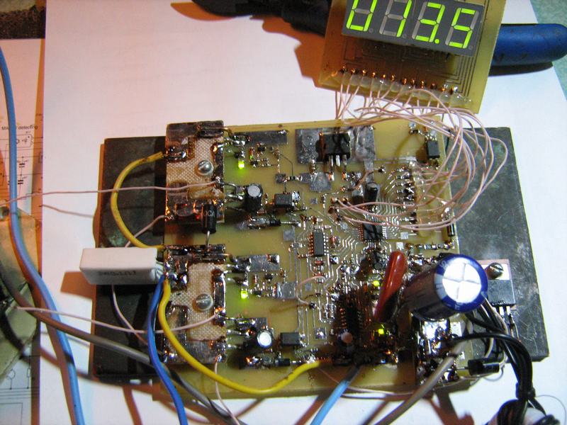
Re: Sinewave inverter prototype.
Thanks Deepone!
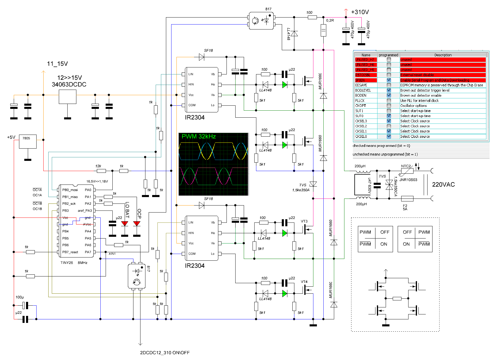
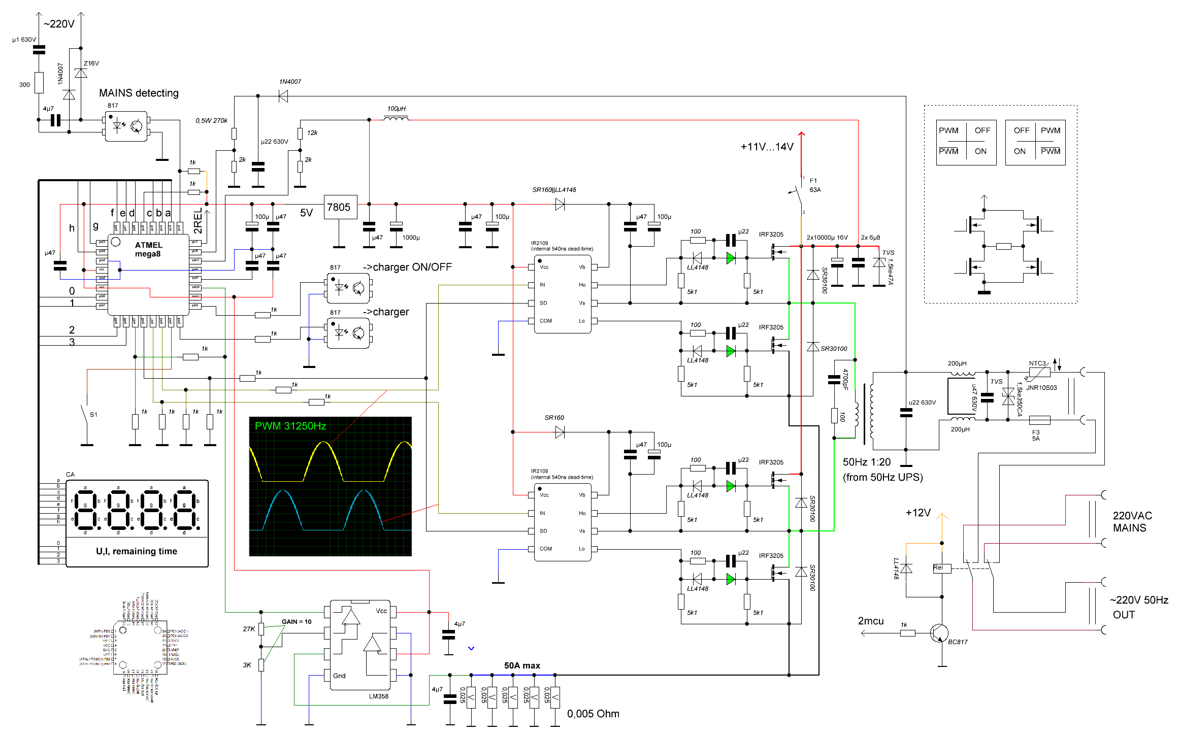
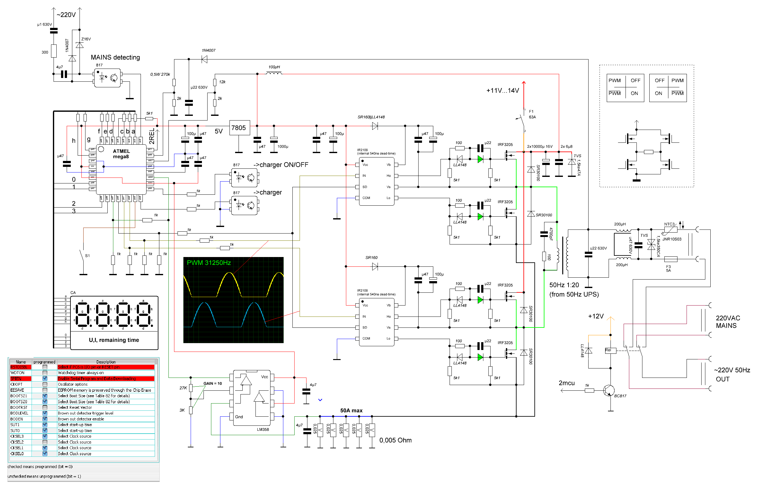
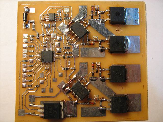
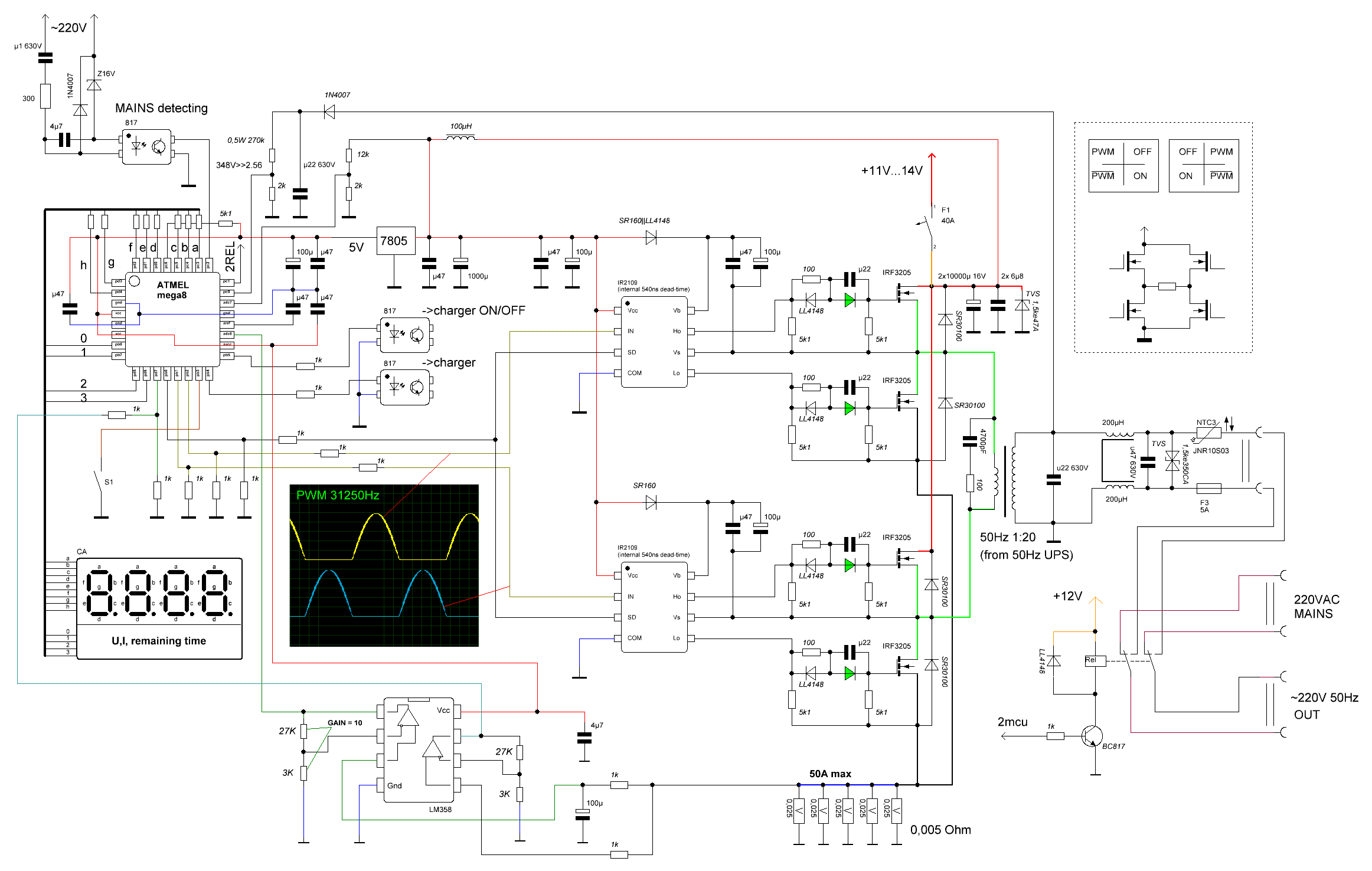
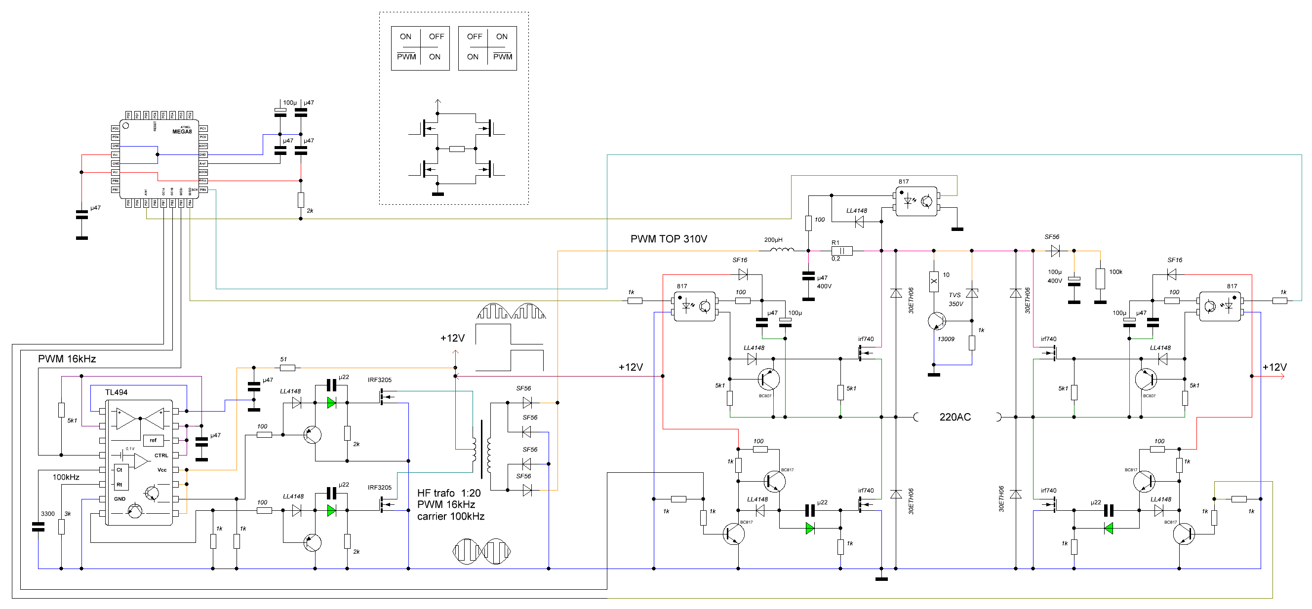
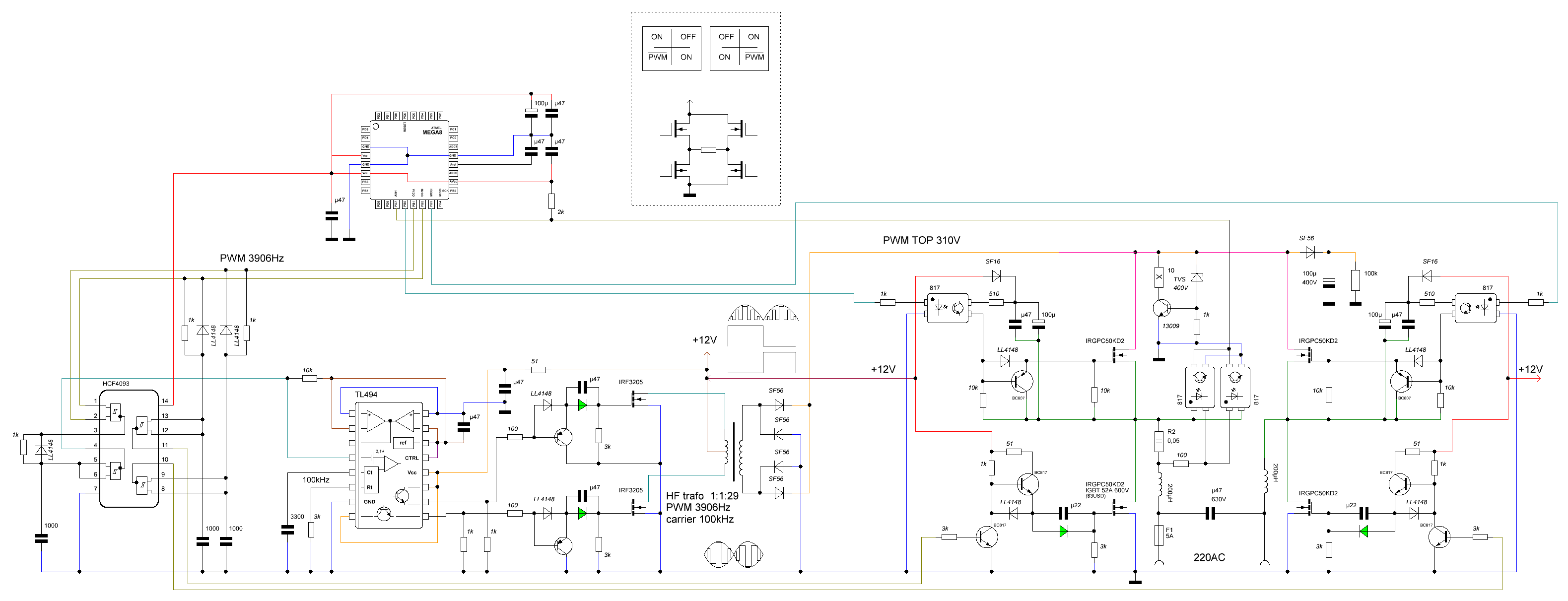
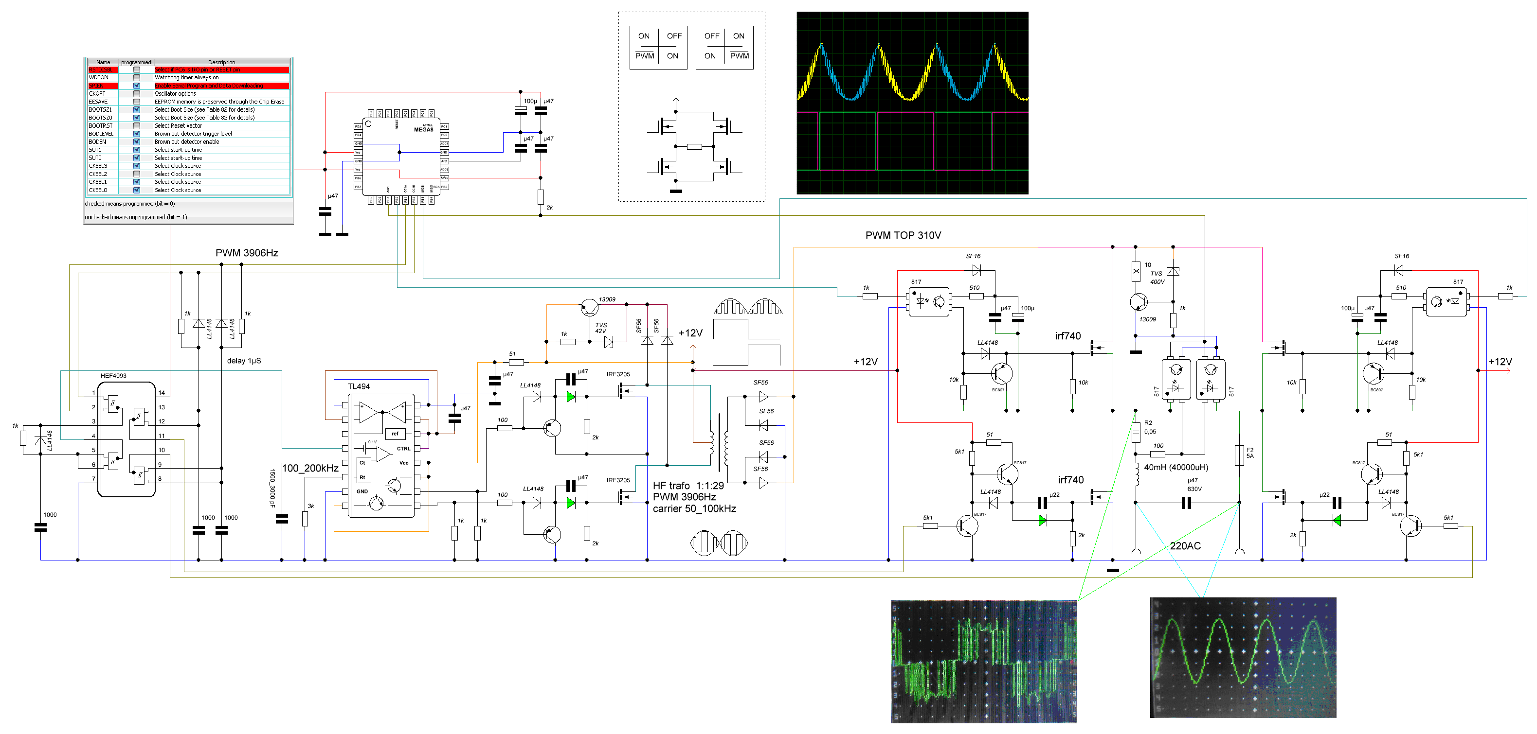
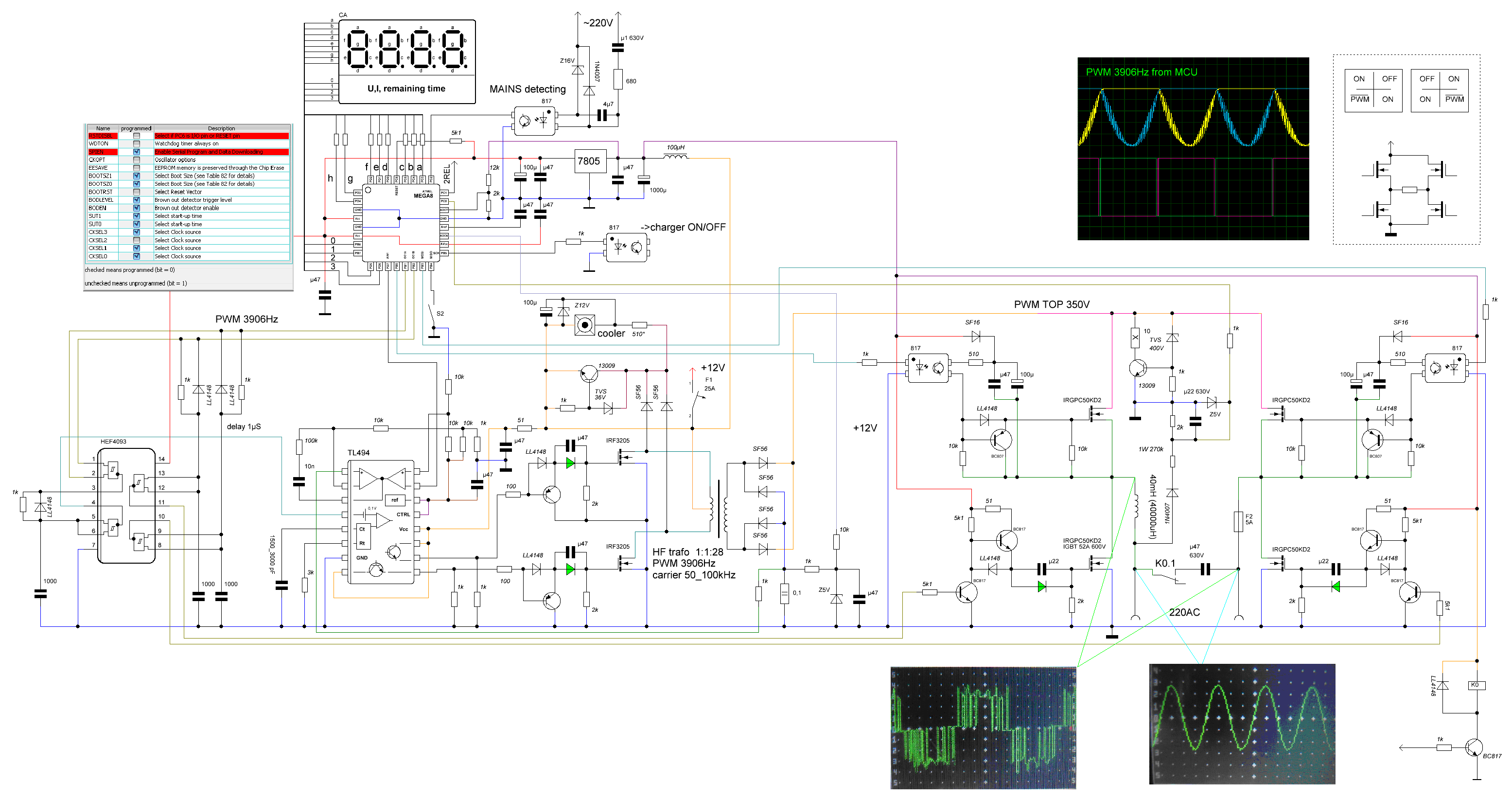
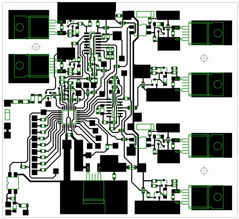
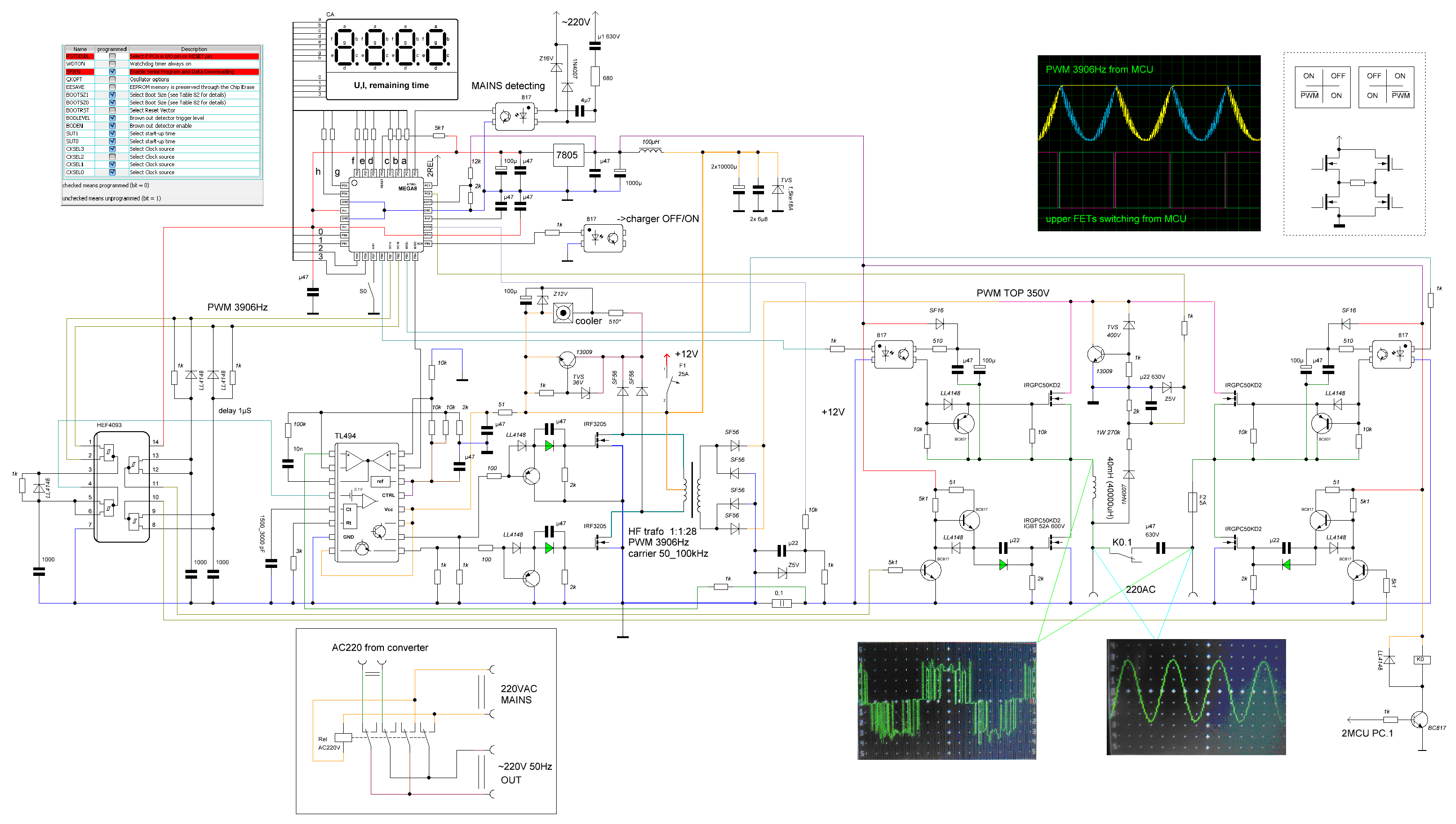
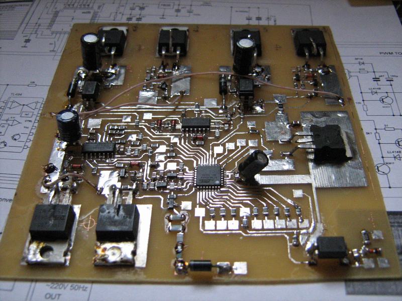
This is implemented using Attiny26 which is hardly available in Pakistan here. The previous one with Atmega8 was good as this IC is widely available here. moreover does this new scheme implies feedback for output voltage correction.
Thanks Deepone!
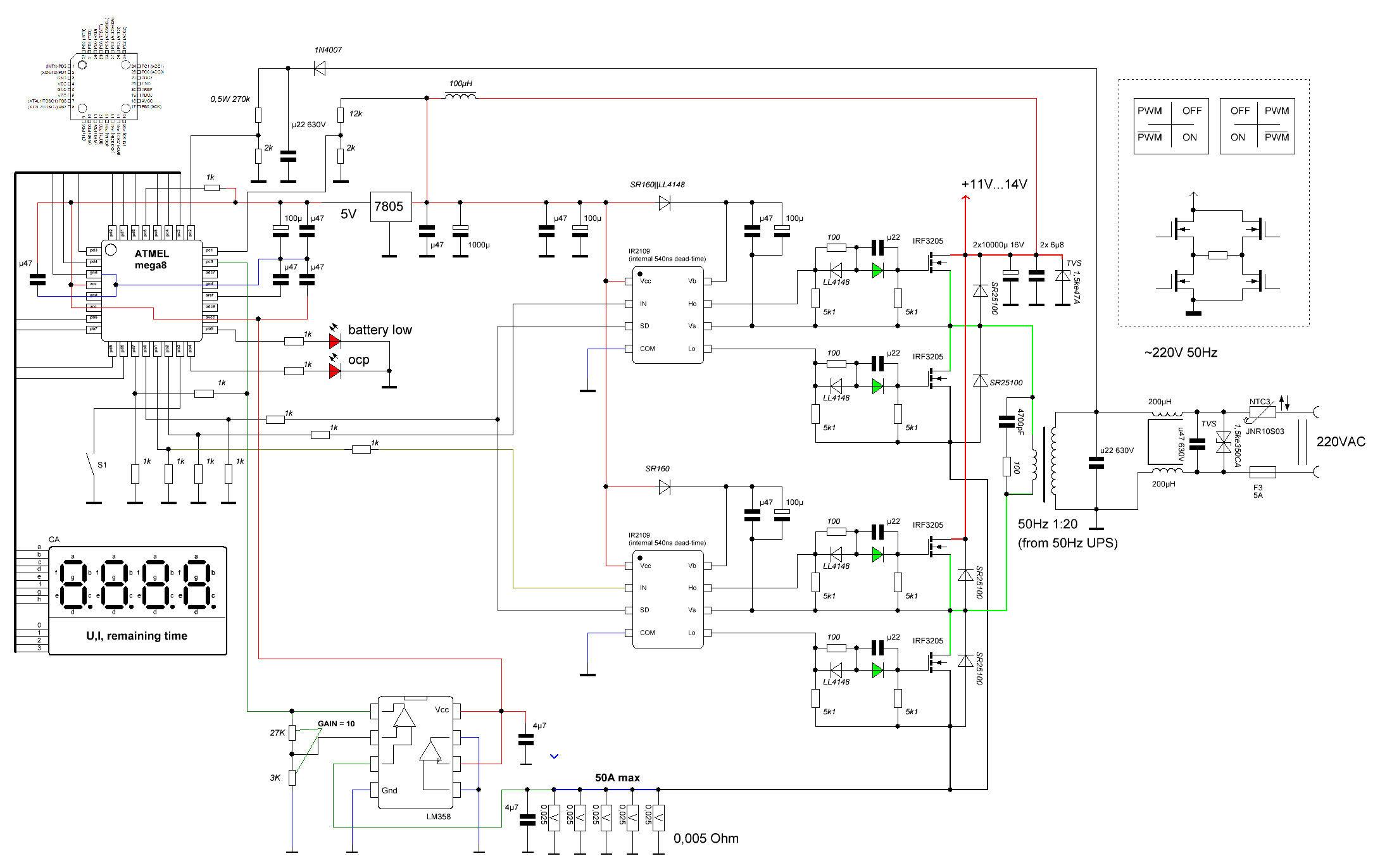
This is implemented using Attiny26 which is hardly available in Pakistan here. The previous one with Atmega8 was good as this IC is widely available here. moreover does this new scheme implies feedback for output voltage correction.