Helena1999
Newbie
Hello everyone,
I recently try to work on LC-VCO. May I ask how is the difference between .tran and .pss >>SIMULATION.
when i simulate by pss, i can see the VCO oscillate. But I use .tran, it didn't work. I simulator the differential vop/von.
Thank you !
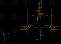
pic 1 is my circuit
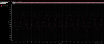
pic2 is pss result
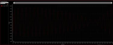
pic3 is tran result
I recently try to work on LC-VCO. May I ask how is the difference between .tran and .pss >>SIMULATION.
when i simulate by pss, i can see the VCO oscillate. But I use .tran, it didn't work. I simulator the differential vop/von.
Thank you !
pic 1 is my circuit
pic2 is pss result
pic3 is tran result