Continue to Site

Welcome to EDAboard.com

Welcome to our site! EDAboard.com is an international Electronics Discussion Forum focused on EDA software, circuits, schematics, books, theory, papers, asic, pld, 8051, DSP, Network, RF, Analog Design, PCB, Service Manuals... and a whole lot more! To participate you need to register. Registration is free. Click here to register now.

[SOLVED] Simulation and PCB are not even similar

Status
Not open for further replies.
Joined
Jun 20, 2022
Messages
5
Helped
0
Reputation
0
Reaction score
0
Trophy points
1
Activity points
107
Hi everyone,

About 1 month ago, I have posted a thread on a similar topic. The topic title is "Basic LC High Pass filter simulation in ADS is not the same with real PCB". The PCB and ADS simulation does not match for cut off frequency. I still manage to do it with valuable comments. Now, I have a little bit different issue.

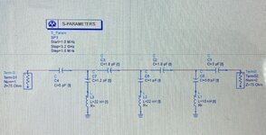
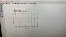
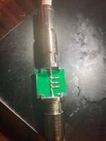
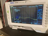
I have designed an easy high pass circuit which can be seen in "im1.jpeg" below. This simulation is made in ADS. You can see the corresponding s21 graph in "r2.jpeg". This circuit is realized with PCB and you can see the simulation in "r3.jpeg" and "r4.jpeg" respectively.

I am not interested in cut off frequency shift for now. I only consider the graph shape which is totally different from the simulation. I know I do not use vendor library components. Also, there is no line in PCB. All components are soldered cascadedly.

The question is : Why do I get different graphs ? Is it because of the input and output impedances ? What can I do to get similar shape of graph with the simulation in PCB ?

Thanks in Advance
 

Attachments

  • im1.jpeg
    im1.jpeg
    220.4 KB · Views: 149
  • r2.jpeg
    r2.jpeg
    454.7 KB · Views: 147
  • r3.jpeg
    r3.jpeg
    102.6 KB · Views: 146
  • r4.jpeg
    r4.jpeg
    94.7 KB · Views: 142

a filter is designed with specific input and output impedances. If you use different impedance than what the design intended, you can’t expect the intended performance.
 

Can you please sketch the PCB stackup used for your filter? I can't decode it from the photo. Also you are apparently using 75 ohm cable connected to a 50 ohm instrument. How is it connected? Did you measure the transmission with the same cables and connector in place of the filter (through calibration)? What's the gain accuracy of the SA used for S21 measurement?
--- Updated ---

I found a magnitude flatness specification for the tracking generator of +/- 3 dB.
 
Last edited:

I believe some of the serial capacitors are cracked or cold soldered. This cannot be explained in other-words.
 

-There is no such dBm(S(2,1)) definition. Can a passive filter have 9dB gain ? Correct it as dB(S(2,1))
-Has the calibration been well done ?
-Components' Values are correct ? Which series did you use ?
-Why don't you use simply SMA type connectors for PCB ? Those connectors which are actually used are bulky and GND connections are poor.
 

According to my experience, it's well possible to achieve acceptable filter performance for around1 GHz cut-off frequency (here 800 MHz) with 0603 chip capacitors and inductors.

The filter is build on a RF veroboard.

1659198174181.png


1659198512885.png


1659198256160.png


1659198297732.gif
 
elliptical function highpass IS a fairly standard one to use.
but at least ONE of your poles is WAY mistuned.

i woud open ciruict two of the elliptical poles (unsolder the capacitor to them), meausre the response on the network analyzer, then go to your simulator, open thos same capacitors, and compare the two responses. IF the tested circuit pole frequency is off, adjust the component values until it is right on the money.
you might need to parallel up two capacitors to form the one value you need. for instance instead of using 1.2 pf, use two caps 0.2 pf in parallel with 1.0 pf. that way you can move the smaller cap up and down in value in -.1 pf steps.

when that one pole is tuned up, reconnect a 2nd pole and do it all over again. and so on.

For these type of filters to work well, you need to select the highest Q for each component that you can find. Getting the high Q inductors is usually the issue--you might need to switch to tiny air coils
 

I would remove all components and make c1=c2=c3=c4=10 nF and measure the insertion loss.
If there is not flat line with loss of about 1dB for your required frequencies, then something is wrong with the connectors and pcb.

There has been comments about the 75 Ohm connector, this is for video and television broadcast, but test equipment is usually 50 Ohm. What happens in ADS if you change impedance ports to 50 Ohm?
 

Status
Not open for further replies.

Similar threads

Part and Inventory Search

Welcome to EDABoard.com

Sponsor

Back
Top