Vermes
Advanced Member level 4
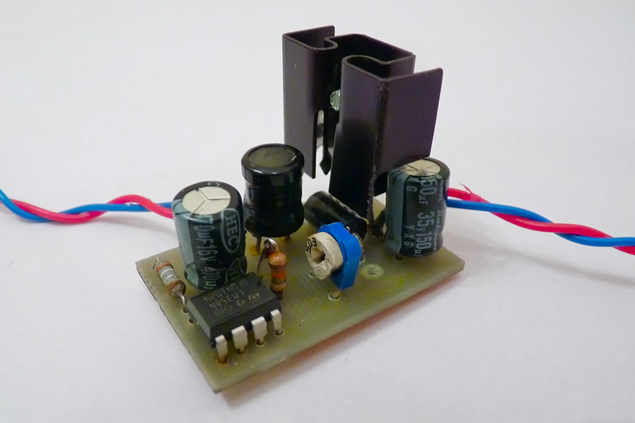
This is a solution for the need of powering a diode (for example, 3W) with the smallest possible loss, from an accumulator that provides several V. Presented here circuit is a unusual application of cheap and simple converter LM2576. To use it as a current stabilizer, you have to search for information on this issue on the Internet.
How do chips of LM2576 type work?
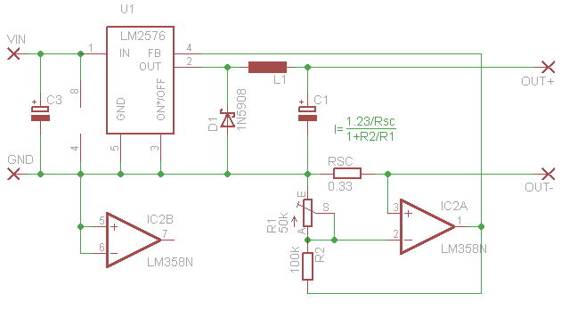
There are two versions of this circuit – adjustable and with predefined voltage. The adjustable one is equipped with pin FEEDBACK that plays the key role in stabilization of the output voltage. This input is used by the converter to measure the output voltage, and correct its work parameters on the basis of this measurement. The measurement is not carried out inside the chip, such as in linear stabilizer 7805. Converter waits for 1,23V on this pin (FEEDBACK). If you want to stabilize voltage, you have to insert a divider at the output, that would provide the part of output voltage to the pin FEEDBACK, for example, 10%, and thus a stable 12,3V would be maintained.
Ohm's law tells us that the current while flowing through a resistor, generates voltage drop on it. If you put a resistor in the ground circuit (next to the output), you will receive 0V at one side and U=IxR on the other side. The converter aims to have 1,23V on pin FEEDBACK. This pin should be connected to the measuring resistor with a value of eg 12ohm. When the load is connected, the converter will select the voltage so that the current flowing in the circuit creates a 1,23V of drop on the measuring resistor. That will take place at a current of about 100mA. No matter what load will be connected, the current will be constant. Unfortunately, since there is a voltage drop, and thus heat goes out. In a case of powering a diode by the current of 700 mA that will be 1.23V x 0,7A = 0,86W.
This can be improved by minimizing the R (P=I^2R). You can measure the voltage drop on a smaller resistor (for example 0,33ohm) and then amplify it few times by using operational amplifier such as LM358. Using the resistor and potentiometer it can be configured as not-inversing amplifier, where the signal of the measuring resistor will be connected as an input, and the pin FEEDBACK of the converter will be connected to its output, as in the picture:
Example:
Now try to set the current of 700mA. At such current on resistor 0,1ohm, you would have a drop of 0,07V. What amplification should be used to achieve 1,23V? It can be calculated from the formula: 1,23 / 0,07 = 17,6. Thus, to achieve current of 0,7A, you should select the amplification of 17,6x and the measuring resistor 0,1ohm.
Output current is expressed by the formula: I=(1,23/Rsc)/(1+R2/R1). If the circuit does not have an amplifier, this formula will be only I=1,23/Rsc, because the measurement is carried out directly on resistor Rsc according to this formula: A=(1+R2/R1).
Efficiency of this construction was calculated to 75% and it increases with consumed current.
Link to original thread - Superprosta przetwornica stałoprądowa do LEDów