Continue to Site

Welcome to EDAboard.com

Welcome to our site! EDAboard.com is an international Electronics Discussion Forum focused on EDA software, circuits, schematics, books, theory, papers, asic, pld, 8051, DSP, Network, RF, Analog Design, PCB, Service Manuals... and a whole lot more! To participate you need to register. Registration is free. Click here to register now.

signal tap quartus II plot and fft

Status
Not open for further replies.

jayeffe

Junior Member level 2
Joined
Jan 22, 2022
Messages
20
Helped
0
Reputation
0
Reaction score
0
Trophy points
1
Activity points
118
Hi everyone I'm working with a Quartus II signal tap and I have a problem.
Given that I know how to export the data from the signal tap, I need to process them in matlab.

I created a signal called ADC_DB and another ADC_DB_filter.
These two signals represent a filtered and unfiltered signal by fir filter.

I tried filtering through HW and found that the filter works. But I have to try to do the same thing through matlab.
When I export the signal tap I have a sample vector and I would like to understand how to go about filtering it


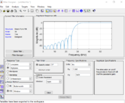
i know filter desiner so i would use the same parameters as fir compiler but the problem i have to do something for the samples.
 

the problem that my signal is a digital signal vector.
how can I do?
 

I don't know what a "digital signal vector" is. When you export your Signal Tap data, you have several options of the data format; "digital signal vector" is not one of them. I suggest you use .csv, which matlab can import directly.
 

I captured the signal from the signal tap.
I need to filter the signal tap signal and display it. I have to compare the filter created with ip core FPGA with the one created in matlab
 

I captured the signal from the signal tap.
I need to filter the signal tap signal and display it. I have to compare the filter created with ip core FPGA with the one created in matlab
That's not a question. But since you don't seem to listen I'll try and be as blunt and straightforward as I can:

Matlab command: y=filter(a,b,x)

x is your signal; a is the filter numerator coefficients; b is the filter denominator coefficients. (I might have that backwards, but, you can look it up). y is the filtered data.
 

I captured the signal from the signal tap.
I need to filter the signal tap signal and display it. I have to compare the filter created with ip core FPGA with the one created in matlab
As barry suggested you can use filter function. You need some care:
1) are you going to use scaled coeffs or normalised ones.
2) how do you control gain, truncation/rounding...i.e how many output bits you are left with and how many lsbs you discard (you can infer that from compiler or experiment in matlab)
3) Matlab filter will have zero initial values. Hardware will be continuous stream so expect mismatch at start/end tails of matlab filter

exactly. The only thing I can't use matlab in my case.
 

exactly. The only thing I can't use matlab in my case.
Use Octave, or build a convolution logic but Octave will do. So what are you planning to use then?

but you said:
"Given that I know how to export the data from the signal tap, I need to process them in matlab." ???
 

Regarding signal tap data import, you can read in exported text files with decimal values directly in Matlab, e.g.

Code:
M = load('Ip_64k_SNR92_PWM_ON.txt');
m = M(:,2)*(125/2^23);
In this case, all lines of column 2 are read into a vector, presuming that the header has been stripped before by a text editor. Alternatively you can restrict the line range in the index expression. 24 bit signed data with a nominal range of +/- 125 are scaled respectively here.

Processing captured FPGA data is particularly useful for real measurements, e.g. to determine signal-to-noise ratio or the noise transfer function of an ADC.

Processing FPGA generated data doesn't make much sense, except for learning purposes. You get exactly the same data from a HDL simulator directly. Quartus FIR compiler is generating simulation models and Matlab test code along with the filter.
--- Updated ---

The only thing I can't use matlab in my case.
Mean, you didn't yet learn how to use it?
 

Regarding signal tap data import, you can read in exported text files with decimal values directly in Matlab, e.g.

Code:
M = load('Ip_64k_SNR92_PWM_ON.txt');
m = M(:,2)*(125/2^23);
In this case, all lines of column 2 are read into a vector, presuming that the header has been stripped before by a text editor. Alternatively you can restrict the line range in the index expression. 24 bit signed data with a nominal range of +/- 125 are scaled respectively here.

Processing captured FPGA data is particularly useful for real measurements, e.g. to determine signal-to-noise ratio or the noise transfer function of an ADC.

Processing FPGA generated data doesn't make much sense, except for learning purposes. You get exactly the same data from a HDL simulator directly. Quartus FIR compiler is generating simulation models and Matlab test code along with the filter.
--- Updated ---


Mean, you didn't yet learn how to use it?
True the standard methodology is to check at simulation level. But At work we also confirm implementation and I usually run automated checks on every build using reference inputs/outputs. This is useful to release a build or not. Occasional failures do occur. It is excessive but useful.
 

I managed to create the filter..

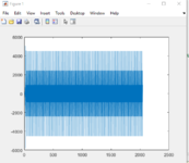
I exported the coefficients, I took the input from the signal tap and only that the plot comes out like this.

i did plot (y)
how can i fix?

i saw that you should do the fft
 

Attachments

  • Immagine 2022-02-05 120244.png
    Immagine 2022-02-05 120244.png
    18.1 KB · Views: 189
  • Immagine 2022-02-05 120850.png
    Immagine 2022-02-05 120850.png
    53.6 KB · Views: 181

I managed to create the filter..

I exported the coefficients, I took the input from the signal tap and only that the plot comes out like this.

i did plot (y)
how can i fix?

i saw that you should do the fft
Your plan isn't clear.
1) Do you want to pass fpga filter input into matlab model and get matlab output and compare fpga output against matlab output?
2) Do you want to check fpga filter response across all bandwidth in matlab?

since you are using single tone I will go for option(1) though it does not cover all bandwidth.
 

exactly 1)

how can i fix the plot?
Fix? you want to prove it is ok or not? matlab function will tell. Generate the output of matlab function and compare. Needs care with scaling issues...
--- Updated ---

exactly 1)

how can i fix the plot?
here is a diagram:

1644060679376.png
 
Last edited:

all clear. but for the FPGA I managed to plot the FFT plot.
I don't understand how to do it even with the y signal.
if i did plot (y) i can't
 

Status
Not open for further replies.

Part and Inventory Search

Welcome to EDABoard.com

Sponsor

Back
Top