Continue to Site

Welcome to EDAboard.com

Welcome to our site! EDAboard.com is an international Electronics Discussion Forum focused on EDA software, circuits, schematics, books, theory, papers, asic, pld, 8051, DSP, Network, RF, Analog Design, PCB, Service Manuals... and a whole lot more! To participate you need to register. Registration is free. Click here to register now.

Series inductors in filter

Status
Not open for further replies.

neazoi

Advanced Member level 6
Joined
Jan 5, 2008
Messages
4,123
Helped
13
Reputation
26
Reaction score
15
Trophy points
1,318
Location
Greece
Activity points
36,955
I have designed a LPF that has two sections. One used a 100nH inductor and the other a 200nH one.
I only have 100nH molded chokes. Can I connect two of these in series to form the 200nH inductor?

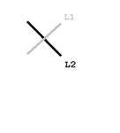
Is there any optimum way I can physically align them (axially, T-form, one next to the other in parallel). I am worrying about weird feedback things, since they are axial.

just a note, these molded chokes have ceramic cores, non ferrite.
 

Mutual inductance of air core inductors can be expected in a low percent range, effectively below initial inductance tolerance of the parts in case of a series circuit.

It's much more a problem for inductors that should be not coupled, e.g. both low-pass sections. Unwanted mutual inductance could reduce filter attenuation in the stop band.
 
  • Like
Reactions: neazoi

    neazoi

    Points: 2
    Helpful Answer Positive Rating
Mutual inductance of air core inductors can be expected in a low percent range, effectively below initial inductance tolerance of the parts in case of a series circuit.

It's much more a problem for inductors that should be not coupled, e.g. both low-pass sections. Unwanted mutual inductance could reduce filter attenuation in the stop band.

So I could connect them in series, for the 200nH inductor, and say leave them axially.
Now how do you propose to minimize mutual inductance between two sections of the filter? Place them like the attached image, in the 3d space (assuming the end of the lines are the end of the coils and looking them from the side)
 

Attachments

  • Untitled.png
    Untitled.png
    2.7 KB · Views: 83

Place the inductors orthogonal to each other where possible. If not possible, place them axially. Never place inductors so that their main axis are parallel. If you have a design with three inductors, place them like this _ | -, or the first one low, the second one perpendicular to the first, then the third one high, also perpendicular to the second.

A three inductor design placed like this |-| will have coupling that will destroy the out-of-band response.
 
  • Like
Reactions: neazoi

    neazoi

    Points: 2
    Helpful Answer Positive Rating
Place the inductors orthogonal to each other where possible. If not possible, place them axially. Never place inductors so that their main axis are parallel. If you have a design with three inductors, place them like this _ | -, or the first one low, the second one perpendicular to the first, then the third one high, also perpendicular to the second.

A three inductor design placed like this |-| will have coupling that will destroy the out-of-band response.

Thanks, I will do that. That is short of what I was looking for.
You are talking in 2-dimentions, but I am building the circuit on air above a copper clad board.
Can this schema you propose be adjusted for even less mutual coupling in the 3D?

For example make it like you said in the XY plane:
_|-

And then rotate the last (right) inductor also in the Z plane (i.e towards you), in order for it to be perpendicular to the first (left) one and not parallel and shifted on the right?

Of course one could use shielding but, let's talk unshielded.

Yes. In 3D, you can get three devices orthogonal to each other. One with its axis aligned with the X-axis, one with its axis aligned with the Y-axis and the last with its axis aligned with the Z-axis. With this configuration, mutual coupling is close to zero.
 
  • Like
Reactions: neazoi

    neazoi

    Points: 2
    Helpful Answer Positive Rating
Status
Not open for further replies.

Part and Inventory Search

Welcome to EDABoard.com

Sponsor

Back
Top