Continue to Site

Welcome to EDAboard.com

Welcome to our site! EDAboard.com is an international Electronics Discussion Forum focused on EDA software, circuits, schematics, books, theory, papers, asic, pld, 8051, DSP, Network, RF, Analog Design, PCB, Service Manuals... and a whole lot more! To participate you need to register. Registration is free. Click here to register now.

Series Resonant Circuit in a 50 Ohm System

chiques

Full Member level 3
Joined
Nov 21, 2007
Messages
168
Helped
2
Reputation
4
Reaction score
2
Trophy points
1,298
Location
California
Activity points
2,534
Hello Forum Peeps,

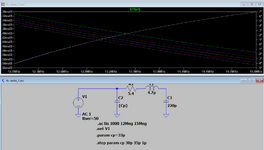
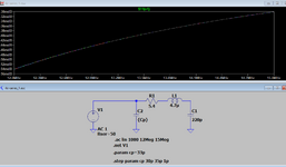
I have a series resonant circuit which I have simulated and built on an actual grounded coplanar waveguide. My question is regarding the Q factor of the circuit. In the case of the LTSpice simulation, I used generic (ideal) lumped resistor, inductor and capacitor. I added this resistor only because my signal generator has a 50 Ohm impedance (not sure if this is correct) although nonexistent on the physical circuit.

1683095796660.png


I’m trying to wrap my head around the fact that even in an ideal world, my circuit Q will only be as high as 9.1.

1683095840885.png


1683095848550.png


Am I using the correct R or is this more like the DCR of the inductor?

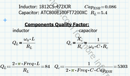
For example: CoilCrafts 1812CS-472XJR is specified to have a DCR of 5.4 Ohm and a Q of 63.

1812CS-472XJR_ 4.7 @ 7.9 MHz 5 63 @ 50 MHz 115 5.4 230

https://www.coilcraft.com/getmedia/677afbbb-f368-4f0b-b59e-ab9befcb1f0e/1812cs.pdf

What about the capacitor, won’t that affect the Q factor the circuit as well?

I’m asking this because I’m currently using a high current pulse inductor PA4548.472NLT (seen on my board) but the datasheet does not show Q. I noticed many high current inductors such as this do not have a specified Q. Is this because they are not intended to be used in RF? I'm guessing the Q is so bad they don't want to publish it..???


My goal is to get a better return loss than -12.8dB

1683095890998.png
 
If your goal is to get a return loss better than -12.8dB, you don't have to use a series resonant circuit.
You need an LC matching network, perhaps just a Γ network will do the job. For this you need to know the input impedance of your circuit.
 
even in an ideal world, my circuit Q will only be as high as 9.1

I think your topic is loaded Q vs. unloaded Q.
Have a look here:

Quote:
When the external circuit is connected to the resonator, the resonator is considered loaded. In this loaded condition, the Q-factor of the resonator is influenced by external circuit elements. The Q-factor of the resonator in this loaded condition is called the loaded Q-factor, which is different from the unloaded Q-factor. The resonant frequency of the resonator also varies slightly with loading. The loaded Q-factor QL can be given by the following equation:

1QL=1Q0+1Qex


Qex is the external Q-factor:

Qex=2f0CGex
 
If your goal is to get a return loss better than -12.8dB, you don't have to use a series resonant circuit.
You need an LC matching network, perhaps just a Γ network will do the job. For this you need to know the input impedance of your circuit.
My goal is to maximize the current going through L and C. If I look at the equation for this it seems 'R' is the limiting factor.

1683152801703.png


Reading this, the 'R' is what determines the Q of the circuit. I guess I'm confused whether this is R (impedance) or R like ESR
 
L:C ratio is a key factor regarding Q and impedance.

Large L, large impedance, large Q.

Small L, Low impedance, low Q.

Since your source is a Sinewave, see if calculations steer you to achieve identical voltage swings on all three, R C L.

Or you may have additional considerations in mind. Example, do you want maximum power transfer?
 
You achieve maximum current in resonance, Imax = Vsource/(50 + ESR)

Total LC resonator ESR is constituted by coil DCR + frequency dependant winding losses + core losses + (small) capacitor ESR.
 
Last edited:
So, you have two goals, first to get return loss better than -12.8dB and second to maximize the current through the series LC circuit.
These goals are not the same, actually they are totally different..
 
Wireless power transfer at 13 MHz?

I think you want to change your circuit structure, and create a parallel resonator that is coupled * to you source, The coupling method and coupling factor needs to be found, direct series connection is not the solution here because the loaded Q is too low (50 Ohm source in series with LC)

Did you check papers on that topic? I'm not into that topic, but see circuit example below:
 
So, you have two goals, first to get return loss better than -12.8dB and second to maximize the current through the series LC circuit.
These goals are not the same, actually they are totally different.
Not necessarily totally different. Matching your source impedance (e.g. 50 ohm) to LC circuit real impedance in resonance fulfills both, maximum power transfer (s11 = 0) and maximal inductor current.

It makes only sense if the test setup models a transmitter circuit, as guessed by volker@muehlhaus. You'll determine the actual source and load impedance before designing a matching circuit. It's unlikely that the LC resonator directly matches the source impedance, neither in series (too low) nor in parallel circuit (too high).
 
If your goal is to get a return loss better than -12.8dB, you don't have to use a series resonant circuit.
You need an LC matching network, perhaps just a Γ network will do the job. For this you need to know the input impedance of your circuit.

L:C ratio is a key factor regarding Q and impedance.

Large L, large impedance, large Q.

Small C, small impedance, small Q.

Since your source is a Sinewave, see if calculations steer you to achieve identical voltage swings on all three, R C L.

Or you may have additional considerations in mind. Example, do you want maximum power transfer?
Voltage across the inductor and the capacitor are close, the voltage across the resistor is much lower.
1683228645267.png


Q factor of each component:
1683228760517.png


Yes, maximum power transfer is the goal. That's why I'm trying to improve my return loss (S11)
--- Updated ---

So, you have two goals, first to get return loss better than -12.8dB and second to maximize the current through the series LC circuit.
These goals are not the same, actually they are totally different..
I'm confused. I'm trying to achieve maximum power transfer. When I connect this circuit to my PA, I'm seeing ~20% of the waveform reflected.

1683229215749.png


My thinking is if I improve the return loss, this will increase the amplitude within the resonating elements. In other words, a higher Vpk across the inductor and capacitor, the more power will be dissipated.
 

Attachments

  • 1683228682469.png
    1683228682469.png
    60.7 KB · Views: 73
Last edited:
Unfortunately you didn't yet clarify what your application is.

The reflection factor calculation above is nonsense. You say, 50 ohm resistor is modeling source impedance. Respectively it's not part of the load impedance. The reference plane for s11 measurement is between 50 ohm resistor and LCR load.

Adding a series resistor generates additional losses and and reduces power transfer to the load. Instead you want a lossless LC matching circuit for maximum power transfer, as already suggested in post #2 by vfone.
 
Unfortunately you didn't yet clarify what your application is.
My apologies, I read this as being a rhetorical question. The application is to heat up the inductor and characterize the resonant frequency drift caused by the heat rise.
The reflection factor calculation above is nonsense. You say, 50 ohm resistor is modeling source impedance. Respectively it's not part of the load impedance. The reference plane for s11 measurement is between 50 ohm resistor and LCR load.
This answers one of my questions, the resistor in series is not part of the load. That is correct, the beginning of the load measurement begins at the entry of the inductor.
1683235363166.png

Adding a series resistor generates additional losses and and reduces power transfer to the load. Instead you want a lossless LC matching circuit for maximum power transfer, as already suggested in post #2 by vfone.
If I understand vfone correctly, I need an additional LC matching network in between my source and load. Also, in the impedance equation, would the correct 'R' would be the (loss of the inductor + ESR of the capacitor)…?

1683234992728.png


This changes the load impedance to ~ 5.5Ohm
1683235048761.png


1683235112610.png
 
[Edit] Analysis wrong due to LTspice bug.

Series-parallel resonator

1683274536322.png

--- Updated ---

Or even simpler, pure parallel resonance. My assumption in post #9 was wrong

1683275509965.png


In the real circuit, cp should be tuned to compensate for inductor winding and PCB capacitance.
 
Last edited:
Perhaps I miss something because I couldn't see yet a clear definition of the output 'load' other than it is related to the resonant coil. Does it have a value? Or it is strictly the usual losses of a coil (which is not a useful power, I guess). But there is also the possibility that the power of the coil heat dissipation could be useful in the application of interest.

Kerim

Added:
Sorry, only now I noticed we are in the RF forum.
So, I wonder if the equivalent resistance of the RF radiated power could be known. I guess it depends on the nearby objects.
 
Last edited:
Although not clearly stated initially, the OP wants maximum power transfer to the LC resonator ESR. Due to small dimensions and low frequency, there's no relevant radiated or magnetically coupled power involved, all losses can be expected inside the components.
 
Although not clearly stated initially, the OP wants maximum power transfer to the LC resonator ESR. Due to small dimensions and low frequency, there's no relevant radiated or magnetically coupled power involved, all losses can be expected inside the components.

This is what I also understood so far. So, I wonder if this topic is simply an academic one that has no practical application (no useful output power).
Or perhaps, its purpose is to maximize the cooling of the input generator by extracting from it the maximum power (when its load is also 50R, assuming it has no internal complex impedance).
 
Series-parallel resonator

View attachment 182642
--- Updated ---

Or even simpler, pure parallel resonance. My assumption in post #9 was wrong

View attachment 182645

In the real circuit, cp should be tuned to compensate for inductor winding and PCB capacitance.
Trying to run this simulation but I don't get what you get.
1683576181193.png
 

Attachments

  • 1683576086609.png
    1683576086609.png
    184.1 KB · Views: 57
  • 1683576114077.png
    1683576114077.png
    121.5 KB · Views: 60
  • rlc-series_1.zip
    556 bytes · Views: 61
Apparently a bug in LTspice .net statement calculation. The simulation setup follows LTspice examples, but it gives completely wrong results.

Present at least in Version 4 bis 17.0.35 (July 2022). Fixed in newest versions. I should have followed my intuition that the parallel resonant circuit can't directly match 50 ohms (post #9). I'll come back if I have time to redesign the matching.

Sorry for the confusion, I must confess I never experienced a serious LTspice bug like this.
--- Updated ---

Turns out that the bug was detected by LTspice users in 2012 https://groups.io/g/LTspice/topic/50200398, but at that time Mike Engelhardt claimed it's not a bug, altough the setup follows LTspice directions. Now it's fixed in V17.1
 
Last edited:

LaTeX Commands Quick-Menu:

Part and Inventory Search

Welcome to EDABoard.com

Sponsor

Back
Top