Continue to Site

Welcome to EDAboard.com

Welcome to our site! EDAboard.com is an international Electronics Discussion Forum focused on EDA software, circuits, schematics, books, theory, papers, asic, pld, 8051, DSP, Network, RF, Analog Design, PCB, Service Manuals... and a whole lot more! To participate you need to register. Registration is free. Click here to register now.

Safety test after repair advice

Gaber Mohamed Boraey

Full Member level 2
Joined
Feb 26, 2015
Messages
149
Helped
4
Reputation
10
Reaction score
10
Trophy points
1,298
Activity points
2,253
Hello everyone

We repair UPS devices, the single phase and three phase , my question regarding the single phase types starting from 700watt capacity to 10kw ups

After replace damaged components, we not sure that everything ok , and we need make safe test, in other words , after replace damaged components there is reliability of “ boom “ for components, it happened many times with us

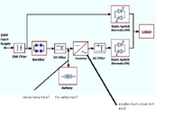
Now I need your help how to isolate the short circuit in the ups “ which is somewhere we not sure yet where “ , in other words when test on battery mode path, how to make safety test , 200 watt lamp as current limiter in series with the ups before battery supply is a solution?, or you have better idea?, if so how about when we have 16 battery or 20 battery ups?, which is up to 30*12v = 360v ?

So if the short circuit still exist the lamp will light?, and save the ups circuits?

attached photo for clarifacation

I hope that clear
Thanks
 

Attachments

  • edaboard.png
    edaboard.png
    119.4 KB · Views: 36
Last edited:
An electronics magazine described building a low-ohm test load for a car battery. It was made from several feet of steel band used to wrap around large heavy cargo. To conserve space it could be looped among nails sticking out of a wood board. Sanding painted spots might be necessary to expose bare steel. Air cooling is 'automatic'. Cabling must be robust as current reaches hundreds of Amperes from a healthy battery.
--- Updated ---

Theater lights were/are smoothly dimmed and brightened by use of a large tank of salt water. It's wired in the current path. Electrodes are lowered into the solution to increase current, raised so a small portion conducts slightly to dim lights.
Thanks for your reply, but I don’t know what you talking about

Anyone can help me here?
 
To do the tests you describe... Incandescent bulbs have always seemed like the easiest method. Versatile. Predictable. In series they reduce current. In parallel they increase current. Designed to tolerate heat. Give us a visual cue that they're operating.

To operate at 360V you can string 2 or more bulbs in series. It's not harmful if they're different Wattage although bewildering results can happen. An article in an electronics magazine points out that 60W and 100W bulbs in series causes the 60W to light more brightly! Behind this is an electrical reason which can be proved via standard formulae.
 
If you are concerned about inrush burnout or undiagnosed faults damaging partial repairs, I would suggest getting a bunch of ICLs which are NTC components and inserting them with PTC resettable fuses to prevent both inrush and then overcurrent after charging up. This requires some analysis I can't offer without details. If that helps determine if the fix is good then it can be bypassed or left in. Without a ZCS, peak surges can be stressful with random phases, with crossover switching from inverter to grid or visa versa.
 
Last edited:
What are
This requires some analysis I can't offer without details.
What details you need know?
I would suggest getting a bunch of ICLs which are NTC components and inserting them with PTC resettable fuses to prevent both inrush and then overcurrent after charging up.
Can you show simple drawing explain this idea?, or resource where I can read about this?
 
What are

What details you need know?

Can you show simple drawing explain this idea?, or resource where I can read about this?
No.

Lookup the component specs and estimate the average current or power relative to the rated current or power at critical nodes.

If you don't have the analytic skills to read schematics and reverse engineer the design specs, what can I say about every repair you do?
 
No.

Lookup the component specs and estimate the average current or power relative to the rated current or power at critical nodes.

If you don't have the analytic skills to read schematics and reverse engineer the design specs, what can I say about every repair you do?
Okay
 
Hi,

Title says "safety tests" ... but the discussion seems to be about "functional test".

For safety tests I rather expect high voltage isolation test and so on.

Klaus
 
Which one are you focussing? Headline says safety test.
Safety test sir, it’s just my expression for the kind of help I need

All what I need is a method to save components from damage after replace because if there is still a fault

Can I use series lamp with the battery source?, or there is a better method?

Hope I’m clear now
 
From wiki;

Electrical safety testing is a process that checks if electrical systems follow specific safety rules to keep people safe. By conducting these tests, we make sure that the electrical devices and systems we use meet certain standards to prevent accidents like electric shocks or fires. It's important to test regularly to ensure everything works properly and keeps us safe.
Some types of electrical safety tests include:
Gaber meant he wants to "safely" test his repairs from burning out again due to some other primary fault not found yet. This can get expensive.

ICLs and PTC's are cheap but unless they are sized correctly, may not function or protect. But at least are unlikely to cause damage.
The same applies to a fuse.
 
Last edited:
Gaber meant he wants to "safely" test his repairs from burning out again due to some other primary fault not found yet. This can get expensive.
Right, thanks for understanding

ICLs and PTC's are cheap but unless they are sized correctly, may not function or protect. But at least are unlikely to cause damage.
The same applies to a fuse.
This concept look like the series lamp , as the lamp have internal resistance also become big when work

What different between using series lamp and ptc?
 
Tungsten is a PTC with 12:1 range in resistance hot:cold but you may be using it over a smaller range in normal use.
Polyfuse PTC's are typically 3:1 range from trip:hold with a wide range of temperature slew rates in between. They are resettable lights like your lights but smaller and come in a wide range of values.

ICLs are NTC so just the opposite like a soft start for charging large caps from the grid. But must be rated for the C*V application. They are meant to run hot with low R but start cold with high R.
1713791223667.png
 
Last edited:
Tungsten is a PTC with 12:1 range in resistance hot:cold but you may be using it over a smaller range in normal use.
Polyfuse PTC's are typically 3:1 range from trip:hold with a wide range of temperature slew rates in between. They are resettable lights like your lights but smaller and come in a wide range of values.
I understand, thanks

But just I remember now that when mosfet burned , I disconnected the voltage source and it stopped burning other mosfets
I’ve noticed two big fuses at the entrance if battery source , after the burn I found they are ok , how you think if I had PTC in series with the battery source?, would it save the mosfet?, or that need a try from me?

Regards
 
Hi,

debugging means you need to understand the circuit, the expected voltages, the expected currents, the expected power dissipation...

In my eyes it´s impossible to set up a power supply and it for different applications.
And one needs to debug section by section.

Example:
A calss A audi amplifier may have an expected power dissipation of 100W. So you can not "safely" debug a 500mW rated zener diode.
If there is a fault in the zener circuit .. you can´t protect it from explosion just by a input voltage limit, input current limit or even input power limit.
(And all active limiters are better than passiv PTCs or ICLs)

Klaus
 
Batteries have very low ESR and so a charger design cannot simply apply a voltage source and must have some controlled current limit. This often results in a voltage rise across the switch at limited current depending on the voltage difference and then the power dissipation can become a problem. Normally this only occurs during transitions of an inductive SMPS so the switch is either in theory ON or OFF but in fact dissipates energy during the transition. Then there is something called the Safe Operating Area or SOA of any transistor that restricts pulse V*A * t with curves and no polyfuse or fuse can prevent this fault. Sometimes FETs with excessive Capacitance can become vulnerable to increased delays of these transitions and increase junction stress.

If the design has a primitive or ineffective current limiter, you may have to modify it and/or maybe increase the peak current sensing resistor so it limits charging at lower current. UPS's usually do not need fast charging, rather work better with high Amp, _us pulses to desulphate the idle battery rather than DC currents. This might be an upgrade to cheap UPS's that your client might appreciate, but then you need to know how to do this.

You can use lower than expected limit ICL's or lamps and not get it started correctly and if nothing gets damaged, slowly increase the holding current values with bulbs in parallel or larger values of ICL leaded discs. Parallel works for PTC and linear resistors with current sharing but not NTC devices such as ICL's.

You will have to experiment with Known Good Boards (KGB) to find a useful range of protection ICL and/or Polyfuse for each product and also learn to use thermocouples on the potential hotspots like SMPS transformers and FETs with Kapton Tape to get quick feedback of a problem. A good LCR meter is also a good tool for measuring shorts, capacitors and battery parameters like ESR. Mismatched cells are a major issue without a BMS in the design.
 

LaTeX Commands Quick-Menu:

Similar threads

Part and Inventory Search

Welcome to EDABoard.com

Sponsor

Back
Top