Continue to Site
Follow along with the video below to see how to install our site as a web app on your home screen.
Note: This feature may not be available in some browsers.
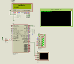
Try the attached project. If you weigh 42 Kgs and the scale gives out 4200000 continuously then it doesn't cause problem because until the weigh value is changed it displays the same data repeatedly. If value changes then it displays new data.
Code C - [expand]
Try this code. I hope it will solve your problem.
Code C - [expand]
Code C - [expand]
There was a mistake in the code. I have fixed it and tested in Proteus. Try this.
Code C - [expand]

You have entered 5487412 between two = and it has displayed it correctly. What else do you want ?
Code C - [expand]
Try this code then.
Code C - [expand]
So there is no way to place the code in a loop and trigger it by a switch, I tried it my self but it didn't work and I've come so close to finish this, don't have enough time at this point to adjust my project direction and read after the op amp circuit.My advice is replace the board in the weighing scale with a new board which gives both LCD output and UART output. Just read the load cell values (after op amp circuit) and write a new code.
Code C - [expand]
No the number received from serial has the value at one end and the ZEROS at the other end so it starts with zeros and end with the number =00000123=00000045 etc0025805000 has to be displayed as 5085200 ?
Then it is easy. I will write a code for you.
Confirm
=000012305= has to be displayed as 50321 ?
Code C - [expand]
Thanks a lot, I tested this code using Proteus and hardware, in Proteus everything works fine, but when I turn to hardware since I receive continuous non stop feed of this format =000240=000090=000088= ...etc
Try attached code. I will post another project after adding button.
- - - Updated - - -
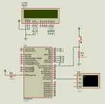
Try this code with new circuit.
Code C - [expand]