Continue to Site

Welcome to EDAboard.com

Welcome to our site! EDAboard.com is an international Electronics Discussion Forum focused on EDA software, circuits, schematics, books, theory, papers, asic, pld, 8051, DSP, Network, RF, Analog Design, PCB, Service Manuals... and a whole lot more! To participate you need to register. Registration is free. Click here to register now.

role of certain elements in MACOM PCB

yefj

Advanced Member level 4
Joined
Sep 12, 2019
Messages
1,195
Helped
1
Reputation
2
Reaction score
3
Trophy points
38
Activity points
7,217
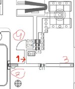
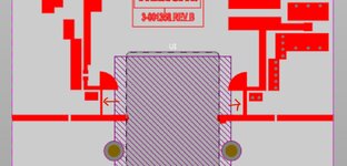
Hello,given the macom amplifier shown below.i have two place which i am not sure about.
1. place marked as 1 in the photo looks like output pin but i am not sure why its needed?
2.in place marked 2 why there is a thick trace with a gap ?
Thanks.
https://cdn.macom.com/datasheets/CGHV1A250F.pdf

1710156546420.png
 
Connector nr. 1 could be a DC current sensor, where the black wire W1 could be the shunt resistor.
Nr. 2 could be the place on the PCB of the big 3300uF capacitor.
 
Hello, given the photo below could you please say where are the 50 ohm lines an where the length sould be lambda/4?
Thanks.
1710361390868.png
 
The lines with the length lambda/4 I marked with an arrow.
These lines are not 50ohms, but high impedance lines (their width is thinner than the width of a 50 ohms line).
 

Attachments

  • L4.jpg
    L4.jpg
    113.8 KB · Views: 35
Hello Vfone,there is a very beig width transition from the place where the trace is touching the VDD(very very thick)
then it have a very sudden transition to very thin width.so i am worried of two things.
1. the transition from very wide to much less wide could cause impedance mismatch.
2.although its based on the manufacturer evolution board the bigger concern is that this trace carrying power to the drain will burn because at the destination the line is very narrow compared to where its started.
how do you reccomend to to the transition?
Thanks.

1710410311518.png
 
Do you mean the "outline" lines at the very beginning and very end, which are not filled? This is a problem with your data import, this must be filled 50 Ohm lines also.
 
Hello Volker , i mean the DC power rail, the RF lines i know it needs to be 50Ohm.
you see that power rail starts very wide then suddenly goes very thin.
if you see some points where it could improve it will be great.
Thanks.
1710417997879.png
 
It is true, theoretically is nonsense to have the DC line very wide and then very thin. But because the DC current is very high (18A) the line should be wider as possible. The line is thin, only in the place where need to be thin, where the line is high impedance.
 

LaTeX Commands Quick-Menu:

Part and Inventory Search

Welcome to EDABoard.com

Sponsor

Back
Top