Continue to Site
Follow along with the video below to see how to install our site as a web app on your home screen.
Note: This feature may not be available in some browsers.
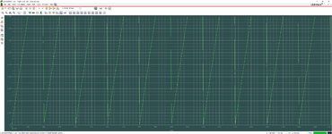
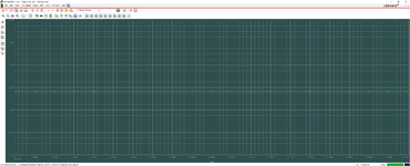
The circuit won't start to oscillate even if the delay is sufficient. It needs a kick start or similar measure due to simulator behavior. 1. It starts in perfect steady state. 2. It doesn't model noise in transient simulation.
Thank you for answering.Yes, kick it with a pulse as FvM mentioned. That's a classical situation in simulating oscillators.
Thank you for answering.Hi
Did you switch to HIGH-Z after the kick started pulse?
What's the expected oscillation frequency?
Klaus
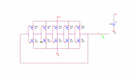
I was trying to build a ring oscillator on Pspice, but it doesn't oscillate..(I posted the output waveform)
PMOS, NMOS L is 0.2um, and Pmos W=4um, Nmos W=1.8um
If you know what the problem is, please give me an advice
Thank you.
VTH: PCH=-0.41 / NCH=0.34Can U answer my questions?
Here 5 GHz @ 3.3 V under 0.25 W https://tinyurl.com/ye2xqxgg Cgs/Cgd=20 Beta=0.05, Vt=0.7
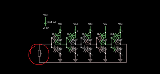
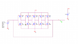
May I ask you how the 1Ohm resistor makes the circuit oscillate? I removed the resistor and the circuit wouldn't oscillate and I don't understand how the resistor is affecting the oscillator.Your circuit oscillates at 500MHx because the Pch RdsOn is too low and Coss of the Nch is too high because it's RdsOn is too low. Try to balance the RdsOn Coss =T for each Nch vs Pch to achieve a triangle wave form with flat rails that match the frequency you wish to achieve = 2 GHz this also depends on the Ciss of each gate.
Then you may succeed , as RdsOn*Coss = T depends on the geometry size of the transistor. (AFAIK) this is a 1st order approximation of a higher order system. This is the same as Coss/gm for a given (Vdd-Vt)^2 if I recall. So increasing the Vdd or reducing Vt will speed up the process as well as lower temperatures.
I would anticipate your Vt shud be around 0.7V . What are Vt and gm or RdsON or Beta? Cds, Cgs? The Pch may need to be enlarged to do this yet have the same Vt , gm as the Nch.
> 5GHz ought to be possible, but this is getting into the realm of CML which operates faster.
no noise is required to kick start it as the slew rate of Ciss, Coss induces current as the outputs invert the input. But if the Loop gain is not >=1 at Vdd/2 , then it will never sustain oscillation. Your target ought to be >>1 and BW -3dB = 0.35/ rise time (10~90%) for the fundamentals and more if the saturation time is a low % for slew time vs prop delay time in the loop. Thus if your gm is enough in 3 stages even higher frequencies may be achieved but with possible asymmetry and duty cycle errors if the Pch, Nch are not well matched.
--- Updated ---
--- Updated ---
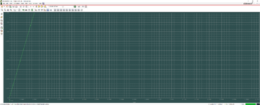
Rough simulation. https://tinyurl.com/ygbjo56p
--- Updated ---
The caps in the FET actually have an ESR which is necessary to prevent violation of KVL with infinite currents or a short circuit. It could be 1 uohm and won't make any difference.VTH: PCH=-0.41 / NCH=0.34
CGS: PCH=6.76E-10 / NCH= 7.68E-10
CDS: PCH= 2.4E-4 / NCH= 2.4E-4
Beta: PCH=1.17E-5 / NCH= 1.07E-5
--- Updated ---
May I ask you how the 1Ohm resistor makes the circuit oscillate? I removed the resistor and the circuit wouldn't oscillate and I don't understand how the resistor is affecting the oscillator.
")