Continue to Site

Welcome to EDAboard.com

Welcome to our site! EDAboard.com is an international Electronics Discussion Forum focused on EDA software, circuits, schematics, books, theory, papers, asic, pld, 8051, DSP, Network, RF, Analog Design, PCB, Service Manuals... and a whole lot more! To participate you need to register. Registration is free. Click here to register now.

RF Receiver Interface to AT89c52

Status
Not open for further replies.
Hi,

budhy said:
1. You use idle_1, it mean when no key pressed the voltage at INT0 is '1'. But why there is idel_1 no data graph? Does it mean without any key pressed there are still a pulses stream on OUT pin?
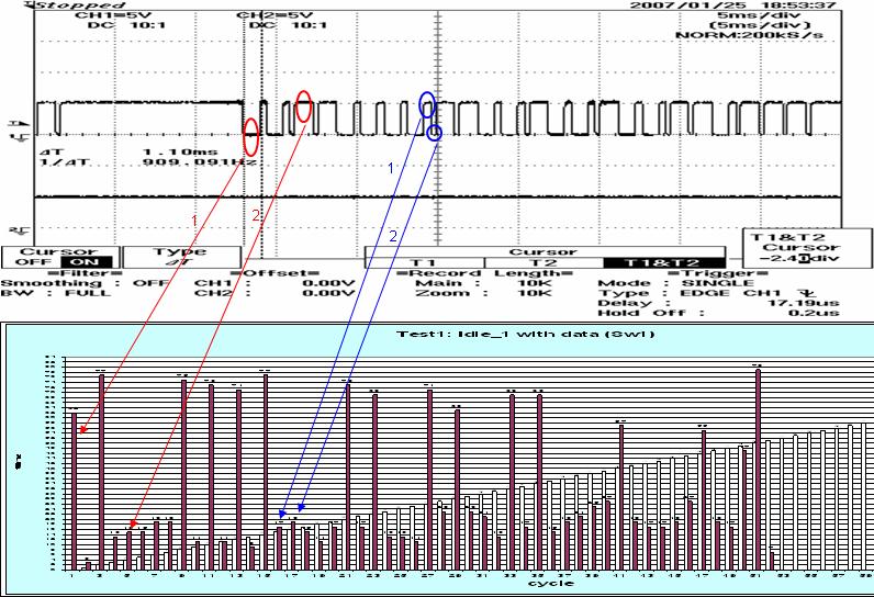
We only can use idle_1 but i am sure the INT0 is '1' when we never connecting the OUT because i got measure it (between the OUT and INT0 i have add one driver Gate 7404, i think from there we already invert the signal already.). Now i also worry whether the OUT signal is stable on Hi/Lo not when no key pressed. If not the 7404 will hap-logic(sometime Hi, sometime Lo). May be because of that we get the idel_1 no data graph. I confirm it again then let you know.

If the OUT signal couse the 7404 signal not stable, what can i do?

budhy said:
2. What is the meaning of CYCLE (blue bar)?
The CYCLE(blue bar) is nothing, it just let us know the number Buffer data. We have 70 data in buffer.

Please check the graph that you wan? If not please me know again.

Thank You.
 

Hi,

I already check the result. I think the Receiver signal is not so stable.
 

Hi,

Here is the actual waveform from Oscilloscope for Transmitter and Receiver.
Please have a look. If anyone know how to solve my problem please help me.

Thank You.
 

Assume the waveform at INT0 as :
85_1169630853.gif


try this
Code:
#define size 70
idata char time[size];

void capture_idle_0(void){
char i,wait;
     do {
         TH0=0; TL0=0; TR0 = 1;
         while (!INT0) ;
         wait = ((256*TH0)+TL0<10000);
         if wait while (!INT0) ;
         ) while wait;
     
     i = 0;
     while (i<=size){
            TH0=0; TL0=0; TR0 = 1;
            while (INT0); TR0 = 0;
            time[i++] = TL0;
           
            TH0=0; TL0=0; TR0 = 1;
            while (!INT0);TR0 = 0;
            time[i++] = TL0;
     }     
}

void main(void){
     TMOD = 0x01;
     IT0  = 0;
     
     capture_idle_0(); // if the idle state on INT0 is '0'
}
 

Hi,

I already capture the waveform for Receiver Signal Driver Output(7404) - INT0 Signal please have a look.

9_1169696551.GIF


The signal to INT0 is not stable will couse the captured Idle_1 time is different. When i doing the experiment, i alway receive data.

I use Idle_1 to capture. Because i got add a driver between OUT and INT0.

I recorded the result on Graph4.
The Key1_pressed more easy to capture.
Key2_pressed and Key3_pressed difficult to capture. Sometime we can't get actual pattern result and sometime i was pressing the key quite sometime then can be capture the result but still can't get accurate result.
I have add the LEDs and use Oscilloscope to measure the result.
Code:
void capture_idle_1(void){ 
char i,wait; 
     do { 
	     P1_0 = 0;

         TH0=0; TL0=0; TR0 = 1; 
         while (INT0); 

         wait = ((256*TH0)+TL0<10000); 

         if(wait)
		 {
		 	while(INT0); 
		 }
         }while(wait); 

     P1_0 = 1;
     i = 0; 
     while (i<=(time0-1)){ 
	 
	 		P1_1 = 0;

            TH0=0; TL0=0; TR0 = 1; 
            while (!INT0); TR0 = 0; 
            time_idle_1[i++] = TL0; 
 
			P1_1 = 1;
           
            TH0=0; TL0=0; TR0 = 1; 
            while (INT0);TR0 = 0; 
            time_idle_1[i++] = TL0; 

			P1_1 = 0;
     } 
     
			P1_1 = 1;

}
 

Sorry, there is a mistake, the right one is:
Code:
     do {
         TH0=0; TL0=0; TR0 = 1;
         while (!INT0) ;
         wait = ((256*TH0)+TL0<10000);
         if wait while (INT0) ;
         ) while wait;
if you can't capture anything, then try this
Code:
void capture_idle_1(void){
char i,wait;
     do {
         TH0=0; TL0=0; TR0 = 1;
         while (INT0) ;
         wait = ((256*TH0)+TL0<10000);
         if wait while (!INT0) ;
         ) while wait;
     
     i = 0;
     while (i<=size){
            TH0=0; TL0=0; TR0 = 1;
            while (!INT0); TR0 = 0;
            time[i++] = TL0;
           
            TH0=0; TL0=0; TR0 = 1;
            while (INT0);TR0 = 0;
            time[i++] = TL0;
     }     
}
 

    Help

    Points: 2
    Helpful Answer Positive Rating
Hi,

This code can't work. If the Key is pressed there are no data capture after release the Key then can be capture.
Code:
     do {
         TH0=0; TL0=0; TR0 = 1;
         while (!INT0) ;
         wait = ((256*TH0)+TL0<10000);
         if wait while (INT0) ;
         ) while wait;

This code working fiine and better then early. No Key hang.
Code:
void capture_idle_1(void){
char i,wait;
     do {
         TH0=0; TL0=0; TR0 = 1;
         while (INT0) ;
         wait = ((256*TH0)+TL0<10000);
         if wait while (!INT0) ;
         ) while wait;
     
     i = 0;
     while (i<=size){
            TH0=0; TL0=0; TR0 = 1;
            while (!INT0); TR0 = 0;
            time[i++] = TL0;
           
            TH0=0; TL0=0; TR0 = 1;
            while (INT0);TR0 = 0;
            time[i++] = TL0;
     }     
}

But how can we conclude the result? At this state the result can acceptable?

Thank You.
 

You'll get a unique space/mark period table for each key, use this unique data to identify which key is pressed
 

    Help

    Points: 2
    Helpful Answer Positive Rating
Hi,

You mean unique space/mark period table = time[] buffer ? If yes, the OUT data is not constant how can we do comparison?

Thank You.
 

You mean unique space/mark period table = time[] buffer ?
Yes! Make a table from each Key!

From your latest Excel file, I see the OUT signal is stable!

if the OUT data is really not stable as you say, then we can't recognize the transmitted signal.
 

    Help

    Points: 2
    Helpful Answer Positive Rating
Hi,

56_1169799869.jpg

Do you know why?
1) Red1 and Red2 time have so much different?
2) Blue1 and Blue2 can't match the graph?
3) After we get the space/mark period table for each key. How we standardize the table for each key? (eg. sometime the Blue1 and Blue2 will match the waveform but sometime not)

Thank You.
 

OK, I think I got it now!
Space/Mark duration is more than 255 uS, so you have to use 2 byte value!

Code:
int time[70];

...
...
   time[i++] = 256*TH0 + TL0;
...
 

    Help

    Points: 2
    Helpful Answer Positive Rating
Hi,

Finally the graph look wonderful already and it quite standard form.

But it have the same problem also. Do you think that is the problem?

At the sametime can you teach me how you record the data in your buffer. I am using AT89C52 the RAM is very small. if my buffer type is unsigned word(2 byte value) and i have 50 data-signal it will eat my microcontrol data~=100. Is it possible we can record the bit in byte to represent the data-result? then it will save data space.

Thank You.
 

If you carefully inspect the graph, the first 20 pulse is about the same, the last 4 pulse is different

Are you agree?

If so, ignore the first section of pulse and use only the last 4 pulse as unique identifier.
 

    Help

    Points: 2
    Helpful Answer Positive Rating
Hi,

Ya, I agree. Thank You.

Thank again for helping me solved my problem. To show my gratitude i would like to give u 100points. Hope you don mind.

Keep in touch..
 

Did you get this to work? I'm trying to use the exact same reciver as you! Could you please give out the working code?
 

zanor said:
Did you get this to work? I'm trying to use the exact same reciver as you! Could you please give out the working code?

Hi,

Yes, It's work. Bellow is the main function. You try to use graph to simulate you result you will see the result very clear.
Code:
void capture_idle_1(void){ 
char i,wait; 
     do { 
         TH0=0; TL0=0; TR0 = 1; 
         while (INT0) ; 
         wait = ((256*TH0)+TL0<10000); 
         if wait while (!INT0) ; 
         ) while wait; 
      
     i = 0; 
     while (i<=size){ 
            TH0=0; TL0=0; TR0 = 1; 
            while (!INT0); TR0 = 0; 
            time[i++] = TL0; // Capture Result
            
            TH0=0; TL0=0; TR0 = 1; 
            while (INT0);TR0 = 0; 
            time[i++] = TL0; // Capture Result
     }      
}

Regard,
Help.
 

I've just started on my project again. I think I have managed to reproduce your program in PIC language.
But how did you get a stable 1 when there is no signal from transmitter?
 

Status
Not open for further replies.

Similar threads

Part and Inventory Search

Welcome to EDABoard.com

Sponsor

Back
Top