Continue to Site

Welcome to EDAboard.com

Welcome to our site! EDAboard.com is an international Electronics Discussion Forum focused on EDA software, circuits, schematics, books, theory, papers, asic, pld, 8051, DSP, Network, RF, Analog Design, PCB, Service Manuals... and a whole lot more! To participate you need to register. Registration is free. Click here to register now.

[SOLVED] Return path

Status
Not open for further replies.

omarelmorsy

Junior Member level 1
Joined
May 9, 2022
Messages
17
Helped
0
Reputation
0
Reaction score
0
Trophy points
1
Activity points
145
Hello,

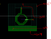
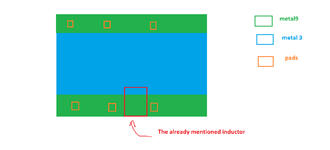
I wanted to know if I have inductor as in image 1, and signal flow from the top to bottom of the inductor, what would be the direction of the return path of the signal ?
would the return path be in the reverse direction on metal 3 ground plane as in path 1 , or would it follow the least resistive path through metal 9 as in path 2 ?

It is worth mentioning that both the ground rail (metal 9) and the plane (metal 3) still extends to the end of the circuit.

Thank you.
 

Attachments

  • Capture.PNG
    Capture.PNG
    23.4 KB · Views: 110

Current will go the least impedance (not resistance) path, so path length also matters (inductance!). From that perspective, path1 looks correct.

You didn't mention how and where metal9 and metal3 are connected, and what return path the attached circuit might enforce due to simple nodal connections of those metals.
 

The circuit continue as the following, the ground plane on metal 3 (large sheet resistance) to the whole circuit around all components, and there are ground rails on metal 9(least sheet resistance) that continue from the start of the circuit tell the end, also ground pads are spread along the ground rail.
metal 9 and 3 are connected using vias.

so I was wondering how the return current might flow, as I want to put sonnet return current ports (-1/-2), but didn't know what is the optimal place to put them
 

Attachments

  • Untitled.png
    Untitled.png
    22.7 KB · Views: 103

This is not easy to answer.

For such cases, some users do full-chip EM that includes much more detail and routing. Some other users do simulation with Momentum where you can have a "ground at infinity" return that means nothing physically, but avoids the losses from metal3 return path seen in Sonnet.

In Sonnet, you must model a closed loop, so I think your only choice in Sonnet is to model the minus terminal connection at metal3. I don't see how the metal9 ground rail would carry current between these minus terminals, it's just too far away.

Disclaimer: We just look at small layout piece here, between two points. For your circuit with more components and routing now shown here, metal9 ground rail might be relevant.
 

metal 3 is connected to metal 9 using vias, so won't current start at 3 (since it is closer )and move to 9 (less impedance ) for example as moving to through metal 9 would be less impedance than continue through metal 3 ?

especially since other components on the sides of the inductor also have rails and their currents might also return through the rail.
one other thing, would it help to use 2 of -1 ports ? one at 9 and one at 3 ?
 

metal 3 is connected to metal 9 using vias, so won't current start at 3 (since it is closer )and move to 9 (less impedance ) for example as moving to through metal 9 would be less impedance than continue through metal 3 ?

I really can't answer because I don't know your CIRCUIT and where the ACTUAL return current will flow. But as said, current uses the least IMPEDANCE path and will prefer shortest path, unless that is MUCH too lossy.

one other thing, would it help to use 2 of -1 ports ? one at 9 and one at 3 ?

Nice idea, but you can't do that in Sonnet. You need to use via ports here at the end of the inductor traces, down to metal3 ground. There is no meaningful way to add another path thru Metal9 in parallel as a second set of minus terminals.

Don't get me wrong - the problem is not Sonnet. The problem is that the physically correct return path (in complete circuit) is not properly defined yet. Your inductor starts somewhere and ends somewhere else, and nobody knows where the circuit around it will close the loop. Such cases are very common for inaccurate results because you model something in EM --- and build something else in your hardware where current flows differently.
 
So what if the inductor is grounded from port 2 using vias to the plane ?would the return path be defined in this case ?
 

Sure!

If you have that connection in simulation and hardware, such a model will be very accurate. Everything is clearly defined where currents will flow (in simulation and in operation).

Return path is not some strange concept for simulation, it is about currents in your circuit. We want to have the same current path in hardware and simulation, because it can change circuit response. Current flow in inductor has an effect, but current doesn't stop there, so the rest of the connection (to form a closed loop) has an effect as well.
 

Status
Not open for further replies.

Part and Inventory Search

Welcome to EDABoard.com

Sponsor

Back
Top