Continue to Site

Welcome to EDAboard.com

Welcome to our site! EDAboard.com is an international Electronics Discussion Forum focused on EDA software, circuits, schematics, books, theory, papers, asic, pld, 8051, DSP, Network, RF, Analog Design, PCB, Service Manuals... and a whole lot more! To participate you need to register. Registration is free. Click here to register now.

Repeat on/off delay Timer

Status
Not open for further replies.
Sorry Len for not being too clear in my previous post.

In case of single LEDs, I meant by different drivers, just the different limiting resistors. And since I usually design circuits for consumers and some circuits are assembled manually when their quantity is not big, my assistants need to be more careful in placing the different resistors than if their values were equal.

On the other hand, I produced red and green modules (16 * 8 pixels), if cascaded they will form a simple long moving message sign. Each pixel is made with 4 LEDs (2 branches of 2 LEDs in series). In case of red module, a 5V power supply is good. But since the green LEDs needs 3.3V instead of 2V, I had to supply them with 7V instead.

I think you got the idea now.

Kerim
 

ljcox

This is what i think? How this timer circiut is functioning. But? I still may, not be right.
The crystal resonates at 32.768khz. It pluses 8secs on 8sec off. For a period wavefrom of 16sec total.
With an output FQ of 0.00625Hz. So. U1 is the timing clock for the circuit.
If you take 524288 & divide it by 32768 = 16secs period.

What I don't understand? How long dose it take to flip high at the 524288bit Q19 .Or is it already set to pluse at 8s on 8s off.
with an output FQ of 0.00625.

Dose the 4520 IC counter count to 255 and reset every hour for 9Hour (on) then resets its self. Then gos off for 15Hours or do
you need to reset it for 15Hours.If this is correct! I need the circuit to reset it's self each hour,day,week and repeat it each week.
With out me pushing the reset button all the time. Is this going to work the way i stated in Post #1. Just wondering about this.


Please repond.
Thanks.
 

Hi,

Perhaps this may help.

Kerim
 

Attachments

  • 15-9Clock_01.pdf
    13.6 KB · Views: 97
  • Like
Reactions: Ebonic

    Ebonic

    Points: 2
    Helpful Answer Positive Rating
KerimF


Thanks for you input and circuit
I will look into try this out.

I will get back to you.

Appreciate your help.

I still work on the circuit and try to understand what ljcox make for me.

I'm waiting to here from Len to respond to post #43
 

Hi,

It is natural for you to explore all possible methods and choose the best one for you.

On my side, I try making my circuits as clear and simple as possible but this doesn't mean they should be the best solutions to everyone.
Obviously if I have to build such a timer to sell it (to add it to my products for consumers), I would use the smallest MCU to save space, power, money and assembly time :)

Kerim
 
  • Like
Reactions: Ebonic

    Ebonic

    Points: 2
    Helpful Answer Positive Rating
KerimF

It should be 9Hours ON 15Hours OFF. Turning on 8:30AM thur 5:30PM. Then OFF 5:30PM thur 8:30AM.

You have it 15Hours ON 9Hours OFF.Or did you write it backwards.

Can you please! Explain to me. How your circuit is to function.

Thanks
 

I have attached a revised circuit description as I neglected to explain the output gating in the previous one.

Len
 

Attachments

  • Circuit description 1.txt
    958 bytes · Views: 94

Hi,

Perhaps this may help.

Kerim
Kermin,
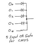
The attached drawing shows how I do diode.resistor gates that interface with CMOS.

You don't need 5 diodes & 1 resistor, you only need 4 + 1.

Len
 

Attachments

  • 5 input OR gate.jpg
    5 input OR gate.jpg
    44.1 KB · Views: 107

Hi Len, my name is Kerim ;)

Since each output is on for 3 hours, for 9 hours ON we need the first 3 outputs only to drive the NMOS, by using 3 diodes and 1 resistor (to give the same Vgs), or as you proposed 2 + 1.
In case you reduced one diode, the output with the resistor will drive the NMOS with a bit higher voltage (adding about 0.6V) than of others.
For most NMOS, this difference may not be noticed at the output mainly if the load is already full on (Vds close to zero by output 0 or 1).

Kerim
 

Kerim

Should i use all diodes on the output and one resistor
or use 4 doides and one resistor as to what Len suggested.

It should be 9Hours ON 15Hours OFF. Turning on 8:30AM thur 5:30PM. Then OFF 5:30PM thur 8:30AM.

You have it 15Hours ON 9Hours OFF.Or did you write it backwards.

Can you please! Explain to me. How your circuit is to function.

Thanks

---------- Post added at 13:47 ---------- Previous post was at 13:45 ----------

Len

This is what i think? How this timer circiut is functioning. But? I still may, not be right.
The crystal resonates at 32.768khz. It pluses 8secs on 8sec off. For a period wavefrom of 16sec total.
With an output FQ of 0.00625Hz. So. U1 is the timing clock for the circuit.
If you take 524288 & divide it by 32768 = 16secs period.

What I don't understand? How long dose it take to flip high at the 524288bit Q19 .Or is it already set to pluse at 8s on 8s off.
with an output FQ of 0.00625.

Dose the 4520 IC counter count to 255 and reset every hour for 9Hour (on) then resets its self. Then gos off for 15Hours or do
you need to reset it for 15Hours.If this is correct! I need the circuit to reset it's self each hour,day,week and repeat it each week.
With out me pushing the reset button all the time. Is this going to work the way i stated in Post #1. Just wondering about this.


Please repond.
Thanks.
 

First I thought when writing the post #50 that Len is Ibonic... Sorry.

Now to Ibonic :)

Are you saying in your post #51 that you didn't understand anything I wrote in post #50?!

Kerim
 

kerim

I'm Ebonic...Not Len. Isn't Len ljcox? His first name is Len.Im assuming.Away.
I wrote post # 43 for ljcox who is. Len!

I wrote in post # 51. Then i reposted post #43 in a reply But? It some how posted in #51.Sorry.

Did you write post #50 for me. If you did.Then my answer is. No! I do not know what you mean.


I just want everyone who post replies in my thread.That. I am. Ebonic!

Thanks
 

Kerim

Should i use all diodes on the output and one resistor
or use 4 doides and one resistor as to what Len suggested. There is no significant difference except that you save a diode. As Kerim wrote, the resistor will increase the gate voltage by about 0.6 Volt compared to the diodes. This will simply turn the FET on harder.

It should be 9Hours ON 15Hours OFF. Turning on 8:30AM thur 5:30PM. Then OFF 5:30PM thur 8:30AM.

You have it 15Hours ON 9Hours OFF.Or did you write it backwards.

Can you please! Explain to me. How your circuit is to function.

Thanks

---------- Post added at 13:47 ---------- Previous post was at 13:45 ----------

Len

This is what i think? How this timer circiut is functioning. But? I still may, not be right.
The crystal resonates at 32.768khz. It (meaning the Q19 output of U1) pluses 8secs on 8sec off. For a period wavefrom of 16sec total. (what you mean is:- the period of the waveform is 16 Sec)
With an output FQ of 0.00625Hz. (1/16 = 0.0625 Hz) So. U1 is the timing clock for the circuit. The crystal driven by the oscillator section of U1 is the timing clock. Each stage of the counter in U1 divides the frequency by 2 so at Q19 the frequency is 32 768/2^19 = 0.0625 Hz thus T - 16 sec.
If you take 524288 & divide it by 32768 = 16secs period.

What I don't understand? How long dose (you mean "does") it take to flip high at the 524288bit Q19 .Or is it already set to pluse at 8s on 8s off.
with an output FQ of 0.00625. See below.

Dose the 4520 IC counter count to 255 and reset every hour for 9Hour (on) then resets its self. Then gos off for 15Hours or do
you need to reset it for 15Hours.If this is correct! I need the circuit to reset it's self each hour,day,week and repeat it each week.
With out me pushing the reset button all the time. Is this going to work the way i stated in Post #1. Just wondering about this.


Please repond.
Thanks.

If you start at the moment U1 is reset (ie. the moment after you release the reset button) then all of the counters are a 0. Q19 goes high after 524 288/2 = 262 144 pulses & goes low after another 262 144 pulses thus completing the period.

I'll anser your other questions after breakfast.

Len
 
  • Like
Reactions: Ebonic

    Ebonic

    Points: 2
    Helpful Answer Positive Rating
Hi Ebonic,

So I guess you have also no idea how the circuit, attached on post #44, functions since my reply on post #50 is about it.
The outputs of the last 4017 IC turn on in sequence every 3 hours (that is 3 hours is the time of one output being on).

After all, if you don't have 6 ICs of 4017 and one 4060 with the 32768 KHz crystal, the circuit I proposed cannot be built ;)

Kerim
 

[/COLOR]Len
Dose the 4520 IC counter count to 255 and reset every hour for 9Hour (on) then resets its self. Then gos off for 15Hours or do
you need to reset it for 15Hours.If this is correct! I need the circuit to reset it's self each hour,day,week and repeat it each week.
With out me pushing the reset button all the time. Is this going to work the way i stated in Post #1. Just wondering about this.

Please repond.
Thanks.[/QUOTE]
There are two 4520 ICs, but it is obvious that you mean U3.

I suggest you re-read the circuit description that I attached some days ago (in post # 48). I think I covered the gating rather briefly in the description, so I'll elaborate:-

If you look at the reset gating, you will see that the output of gate U6c goes High when the count = 24. This is passed through U5c to the reset inputs 1MR & 2MR of U3a & U3b thus both counters in U3 are reset.

So it takes 24 Hours to increment from 0 to 23, then at the next negative edge of the signal on pin 2, it goes to state 24. The gating is designed to detect 24 & thus apply the reset pulse.

Since the reset will occur in about 1 us or less, it appears to us mere humans to go immediately from 23 to 0. But if you looked at this transition on an oscilloscope, you would see the brief transit to 24.

Now, in order to provide the 9 Hr ON & 15 Hr off, the output gating is designed to make the output High while the counter is in states 0 ~ 8 & Low for the rest of the 24 Hr period.

In order to expand on what I wrote before breakfast, I have attached a waveform chart of the outputs of U1.
 

Attachments

  • Waveform chart.jpg
    Waveform chart.jpg
    154.1 KB · Views: 95
Last edited:

So. If i were to put an LED on Q19 it will take about (4 hours) for 262144 pulses high and another (4 hours) for 262144 low before the LED gos high and turns on at 524288bit. Is this right!
 

So. If i were to put an LED on Q19 it will take about (4 hours) for 262144 pulses high and another (4 hours) for 262144 low before the LED gos high and turns on at 524288bit. Is this right!
No! Look at the waveform diagram in my previous post.

It shows that the period of the waveform on Q19 is 16 sec. So the LED will be on for 8 sec & off for 8 sec as the diagram indicates.

Q19 goes High after 262 144 cycles of the oscillator. The oscillator is oscillating at 32.768 kHz. 262144/32768 = 8 sec.

Len
 

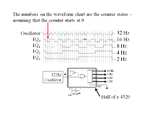
The attachment should help you to understand counters better.

I have drawn an example of how one half of the 4520 IC (without any gating to chnage the modulo) acts as a Modulo 16 counter.

I am driving it with a 32 Hz oscillator. The first stage divides the input frequency by 2.

Each subsequent stage divides the frequency from the previous stage by 2.

So the output frequency at Q3 is 1/16 th of the input frequency.

It is called a Modulo 16 counter as it has 16 states, ie. 0, 1, 2 ..... 15 as shown on the drawing.

If you wanted to make (for example) a Modulo 9 counter, you would have to include gating to detect 10 & then apply a High to the reset intput (pin 7)
 

Attachments

  • Modulo 16 counter.gif
    Modulo 16 counter.gif
    40.4 KB · Views: 108

ljcox

Ok. I took another look at the waveform. as you suggested.

Yes! I understand Q19 has a total waveform of 16sec period. 8secs (on) 8secs (0ff).
So the LED will come (on) for 8secs high,and then go's (off) for 8secs low.Right! This i understand.

What i do not know :-?. Is the 524288bit already divided with the 32.768khz crystal to get the 16sec period.
or dose the counter have first divide by each stage until it gets to Q19 which is 524288bit.


I took this part of your post #58. assuming this is. Correct!
IQ19 goes High after 262 144 cycles of the oscillator. The oscillator is oscillating at 32.768 kHz. 262144/32768 = 8 sec.

So then. Once the crystal is connected to the oscillator the circuit is ocsillating at 262144 cycles for each part of the
waveform which is 8secs on 8secs OFF. Is this Right!
 
Last edited:

Status
Not open for further replies.

Part and Inventory Search

Welcome to EDABoard.com

Sponsor

Back
Top