Vermes
Advanced Member level 4
Presented project is a 230V driver with 8 outputs controller by a browser with ability of viewing the video/videos in the browser.
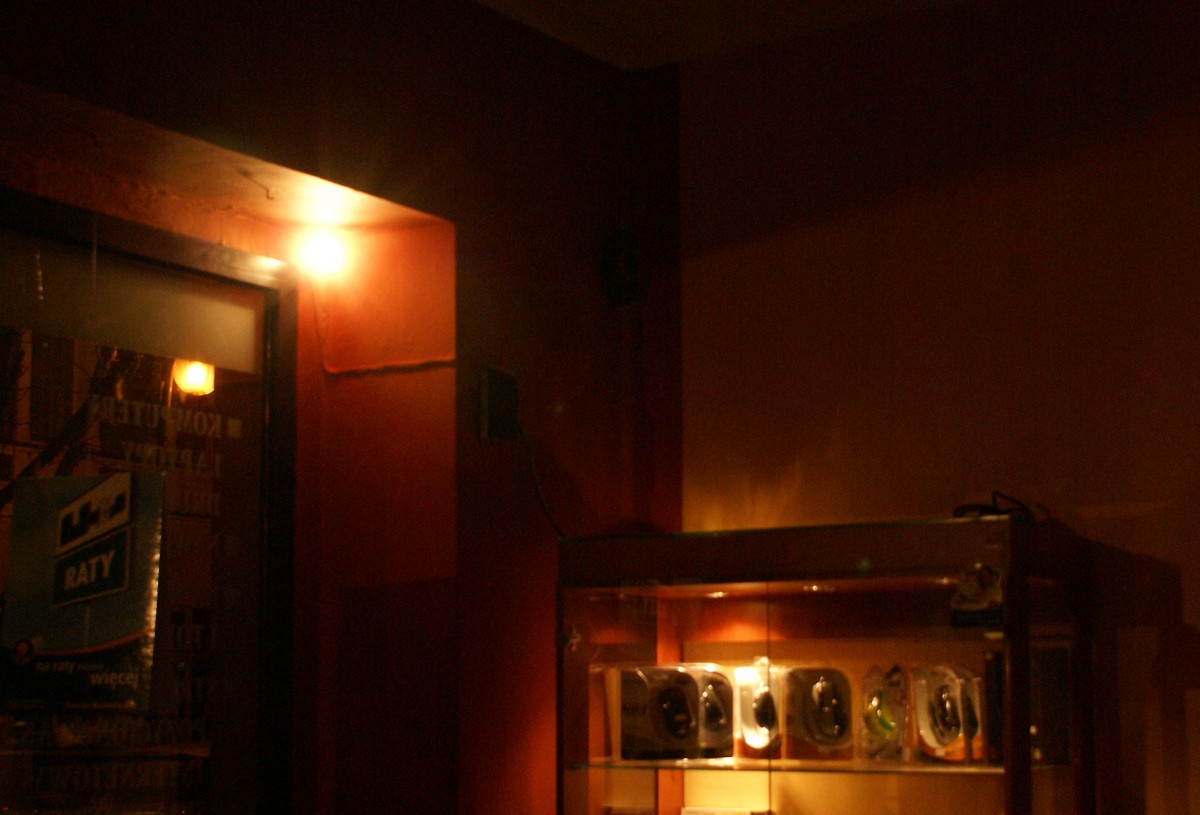
It can be useful when you want to check what is happening in a room where it is installed, without going there e.g. at night.
A separate module of additional lighting (besides ceiling lamps) can be installed in such a place, so as to always ensure that when you turn on the additional lighting, all that is happening, will be clearly visible. Sections of bulbs can be remote controlled in order to change the light, according to particular needs.
Additional light:
USB cameras are connected to the server, on which Slackware (Linux) is installed. A script was written in PHP/HTML/CSS, which sends control signals through the RS232 bus to the executive board, to which relays controlling the operation of individual sections of the lighting are connected.
Atmega16 was used to give a possibility to use Ethernet module separate from the server. This is not included in this project. The control board is divided in two modules – relays module (230V) and module that controls the operation of relays. The board is connected to the server by RS232. RS485 was not used, as the board is installed directly next to the server.
You can use the emergency buttons on the board or the web interface to control the relays (for example, when the server dies).
Below there are some screenshots of the interface. The first one shows additional lighting turned off (view from the camera), the second one - turned on. Dynamic graphics present the relays state. When the relay is turned on, a lamp lights on the web page. Also hours of automatic on/off those sections – so that on Sunday bulbs do not light unnecessarily. The appearance of the interface corresponds to the physical location of the controlled section.


Here, the appearance of fronts, which content the controlled sections (two external bulbs are connected together – the central one separately).

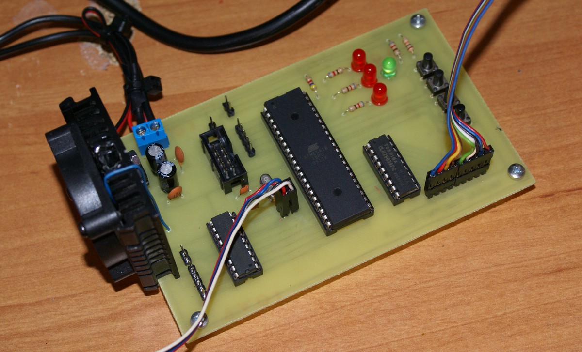
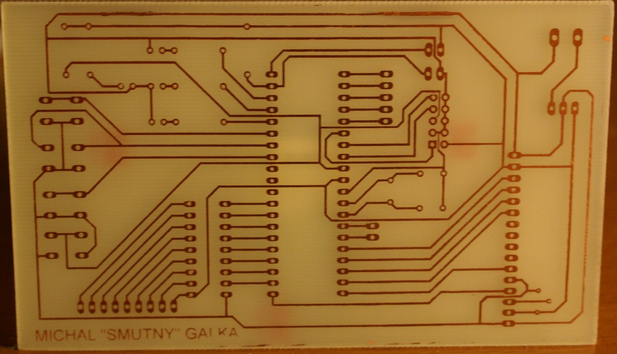
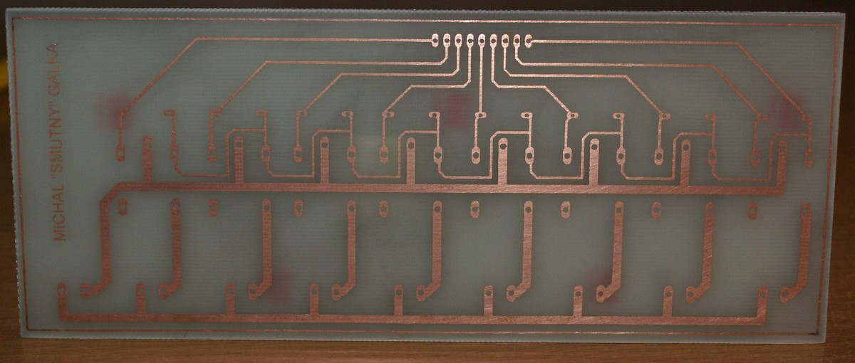
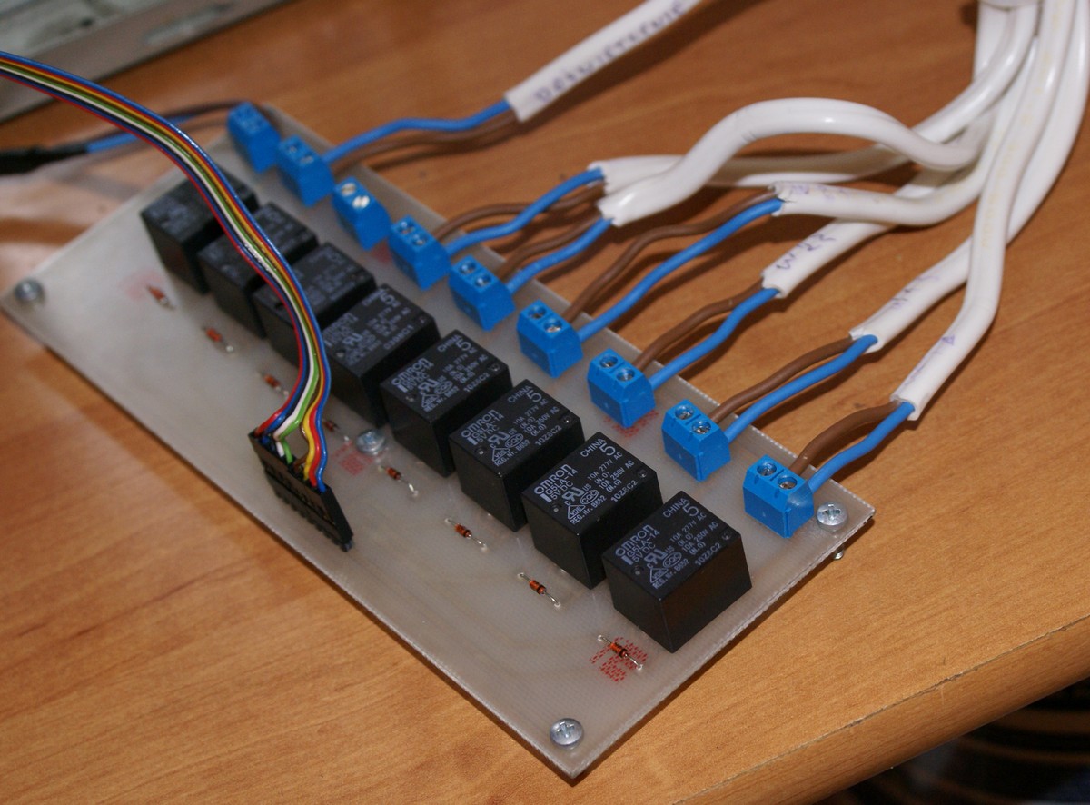
And the view of the electronics:
Link to original thread (useful attachment) – Zdalny system sterowania oświetleniem z interfejsem www