Vermes
Advanced Member level 4
This circuit of lighting control does not have a central control unit. It is a system where every switch will have “direct talk” with the source of light. If the switch and source of light will be equipped with adequately expanded mains modules, all the necessary functions needed for control over the lighting could be implemented without any additional logic drivers.
This will significantly increase the reliability of the system in comparison to a control provided by a central microcontroller, damage of which can cause a long time of not working the system. The lighting at home have to operate without breaks, even if one part gets damages, the rest have to operate properly.
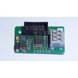
Simple circuit with microcontroller PIC18F14K22 (cheap and powerful) was used as a module of network element. This module can be enclosed in an electrical box.
Features of the module:
- 6 configurable inputs (capacitive touch sensor or contact)
- 4 logic, static and PWM outputs
- output control in different configurations, time changes
- measurement of analog
The executive circuits consist of classical combination of optotriac and triac or optocoupler and MOSFET (for LEDs 12V).
The network is “star-burst” typology – twisted held to each switch and light. The network is a 4-wire one. Electrically it is a symmetrical line. The protocol is based on asynchronous transmission (UART) with a very low speed (4800bps). A packet is 10 bytes.
The system does not have a central logic unit, but the lack of central point would be a problem. In the implementation, wires are grouped into 6 sub-nets, which are concatenated in the switch.
Switch:
- toggles packets from one network to another, if addressing requires that
- allows the access from the “outside” to the network, and therefore any web sites or other domestic appliances are put into the system by the switch
- logs all packets
- generates logic levels and powers the sub-nets
The switch:
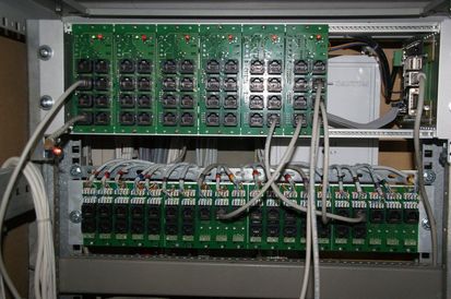
Switch and “cards” of sub-nets are on the top and the “patch-panel” on the bottom.
More information about this project can be found HERE.
Link to original thread - Sterowanie Oświetleniem - system z logiką rozproszoną