RohanDey
Member level 2
Hello,
I have a very strange problem with my circuit, not sure whether the problem is in the relay driver circuit or elsewhere.
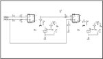
In the attached schematic you can see I am trying to drive 2 relays, (whose output are connected to LEDs for now), using 74LS74 D flip-flops. The pulse (SDA & SCK) to the flip flop comes from a PIC18 uC. The relays need about 5V DC to work.
The problem: When I turn on the first relay, I get about 0.7V on the collector of the first transistor with respect to ground. When I turn ON the second relay I get about 1.2V at the collector of both the transistors. So, with both relays turned on I get approx 3.8V across the relay terminals which is supposed to be about 5V. Now, at some instances due to this low voltage at the relay terminals, the relays don't turn ON even if I send the correct pulse.
I might need to connect more relays to this system.
My hardware connections are: The PIC uC is on a breadboard, and I have made a vero board for each combination of flip-flop, transistor and relay. So, that makes 2 vero boards. All the boards are connected with wires and connectors. The power supply is one 5V SMPS, connected to the bread board. Power supply to the relay boards (vero boards) comes from the bread board through wires.
Another thing which I have noticed is the ground at the entry of the power supply is 0V but on different locations of the entire circuit the ground shows some voltage, i.e. around 0.7 to 0.9V. Also, when the relays are OFF, the ground is 0V at all locations, only when the relays are turned ON, the ground at different locations start showing some voltage. Not sure how the ground is showing minor voltages.
Thanks for reading so far, I am totally stuck with this problem, so any ideas or suggestions are highly appreciated.
Thanks..
I have a very strange problem with my circuit, not sure whether the problem is in the relay driver circuit or elsewhere.
In the attached schematic you can see I am trying to drive 2 relays, (whose output are connected to LEDs for now), using 74LS74 D flip-flops. The pulse (SDA & SCK) to the flip flop comes from a PIC18 uC. The relays need about 5V DC to work.
The problem: When I turn on the first relay, I get about 0.7V on the collector of the first transistor with respect to ground. When I turn ON the second relay I get about 1.2V at the collector of both the transistors. So, with both relays turned on I get approx 3.8V across the relay terminals which is supposed to be about 5V. Now, at some instances due to this low voltage at the relay terminals, the relays don't turn ON even if I send the correct pulse.
I might need to connect more relays to this system.
My hardware connections are: The PIC uC is on a breadboard, and I have made a vero board for each combination of flip-flop, transistor and relay. So, that makes 2 vero boards. All the boards are connected with wires and connectors. The power supply is one 5V SMPS, connected to the bread board. Power supply to the relay boards (vero boards) comes from the bread board through wires.
Another thing which I have noticed is the ground at the entry of the power supply is 0V but on different locations of the entire circuit the ground shows some voltage, i.e. around 0.7 to 0.9V. Also, when the relays are OFF, the ground is 0V at all locations, only when the relays are turned ON, the ground at different locations start showing some voltage. Not sure how the ground is showing minor voltages.
Thanks for reading so far, I am totally stuck with this problem, so any ideas or suggestions are highly appreciated.
Thanks..