Continue to Site

Welcome to EDAboard.com

Welcome to our site! EDAboard.com is an international Electronics Discussion Forum focused on EDA software, circuits, schematics, books, theory, papers, asic, pld, 8051, DSP, Network, RF, Analog Design, PCB, Service Manuals... and a whole lot more! To participate you need to register. Registration is free. Click here to register now.

Radio transmitter (Help beginner)

Status
Not open for further replies.

waulu

Newbie level 2
Joined
Feb 27, 2014
Messages
2
Helped
0
Reputation
0
Reaction score
0
Trophy points
1
Activity points
31
Hello,

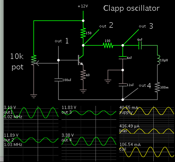
I am designing and building a simple radio transmitter just to practise my electronic skills and learn a little bit more. I started by designing a clapp oscillator, which produce a sine wave with a fundamental at 1 MHz (the goal), and many harmonics at 2 MHz etc. My first question is if I should add a band filter to try to reduce the harmonics?

clapp1mhz.jpg
Clapp oscillator

FFT_Oscilloscope.jpg
FFT of the signal generated by the oscillator

Next I added a mixer to modulate the signal and the carrier. I present a graph with the waves of the signal, oscillator and the modulated signal. My questions are: How can I isolate the oscillator signal so it doesn't get modulated? Should I add a matching network between the oscillator and the mixer? Is the modulated signal acceptable or is it too weak?

modulator.jpg
AM modulator

Bench.png
Bench where I test everything

Singal_Osc_Out.png
Oscillator (red), signal (blue) and modulated signal (green)

FFT_Modulated.jpg
FFT of the modulated signal

I have the arrl handbook and they present alot of schematics with transformers, can someone explain me the purpose of that transformers? Are that a matching network?

WP_20161230_16_32_06_Pro.jpg
Bipolar transistor mixer

Thanks
 

A pure sinewave has no harmonics. Your oscillator has many harmonics because its output is a sawtooth or is squarish instead of being a sinewave. It will cause a lot of radio interference.
 

You oscillator is pulled by simple transistor mixer and its frequency/amplitude is shifted by modulating signal.Any matching circuit is not necessary @ 1MHz but you should evaluate your circuit with elegant circuits such as double balanced mixer.Or you can isolate your oscillator by adding an extra buffer circuit.Meanwhile, your oscillator output can be filtered and cleaner oscillator signal will also clean modulated signal.
 

To reduce harmonics, it helps if you can get sine waveforms through all parts of your circuit. If you allow a waveform to hit a supply rail, then you usually get clipping somewhere.

The bias needs to be adjustable, so that you can find the point where it is just strong enough to maintain your desired output amplitude.

I've collected several variations of the Clapp oscillator. All have one connection of the LCCC tank node to a ground. Some also have another node connected to the emitter leg.

Here is a simulation to compare with your schematic. It is different from yours but that doesn't mean it's best for doing what you intend to do. It is interesting because it portrays sine waveforms with no clipping (theoretically).


The modulated signal waveform suggests that you should urgently learn basics of amplitude modulation, useful modulation index (or "amplitude") and how to achieve it. The waveform shows terrible overmodulation and respective signal spectrum. Suitable at best for a jammer.

https://en.wikipedia.org/wiki/Amplitude_modulation
 

Thank you all. After reading your response and a break of a few days I was able to obtain a better result. I was a little bit confuse about how the output should look.

Modulated.png
Modulated signal

It has a low modulation index but I will improve it later.

I was curious about the balanced mixer and decided to give it a try based on a schematic of the arrl book.

BalancedAM.png
Double Balanced mixer

ModulatedBalanced.png
Output of the balanced mixer

BenchBalanced.png
Bench

I am very confused about the different kinds of AM modulation, can you just confirm if I am getting good results now? With the first mixer a get modulation DSB-FC and with the second I get DSB-SC, right?
 
Last edited:

Perhaps you should clarify the tread title. I understood "Radio Transmitter" as a device that can be received with a regular AM receiver. If so, only DSB with full carrier is of interest.
 

Status
Not open for further replies.

Part and Inventory Search

Welcome to EDABoard.com

Sponsor

Back
Top