T
treez
Guest
Hi,
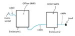
A customer has sent us in a battery charging kit which has failed their radiated EMC. This kit comprises two earthed metal enclosures. (each about 20cm by 20cm by 10cm) One enclosure (A) contains a radio transceiver and a 18W offline flyback smps and a 12w offline flyback SMPS. An isolated 12V cable comes out of this enclosure and goes into another enclosure (B). Here the 12V is stepped down by a 1MHz Buck converter to 5V. This 5V is then used to charge a battery at 2A, by a switch mode charger. (this charger is the only bought in SMPS.)
The peaks of the failure frequencies are approx. 60MHz, 80MHz, 93Mhz , 111MHz and 184 MHz.
In order to find out how to fix this failure, I believe we must use an EMC sniffer (SA1002A by Laplace instruments), and a B field (near field) probe connected to this EMC analyser via coaxial cable. We will use a Laplace instruments SA1020A (Wide band amplifier) to amplify the signal from the (near) B field probe on its way to the EMC analyser.
We will take out each SMPS in turn and simply run it about 6cm below the B field probe. (the B field probe is a ring [loop antenna] about 7cm in diameter). We will see which SMPS gives out the failure frequencies. We will then see if we can do any component changes on the PCB (we are not allowed PCB respins) to solve the failure. We may just have to add cable ferrites etc on the cable interlinking the two units. Or add common mode filters at inputs and outputs to the SMPS’s.
Do you think this is a good ploy? I mean, I presume that the failure frequencies are not due to any beating effects between the various SMPS’s?
SA1002A EMC analyser: