Continue to Site

Welcome to EDAboard.com

Welcome to our site! EDAboard.com is an international Electronics Discussion Forum focused on EDA software, circuits, schematics, books, theory, papers, asic, pld, 8051, DSP, Network, RF, Analog Design, PCB, Service Manuals... and a whole lot more! To participate you need to register. Registration is free. Click here to register now.

R-2R ladder DAC for controlling the gain of the conventional instrumentation amplifier

Status
Not open for further replies.

Junus2012

Advanced Member level 5
Joined
Jan 9, 2012
Messages
1,552
Helped
47
Reputation
98
Reaction score
53
Trophy points
1,328
Location
Italy
Activity points
15,235
Dear all,

For the conventional instrumentation amplifier circuit shown below, I made R4=R3 so I have the gain control reached by Av= 1+2R2/R1

3-s2.0-B9780750611954500063-f02-85-9780750611954.gif


I used to design multi-tapped resistor of R2 to have programmable gain amplifier. However, with many and fine gain setting it cost more switches for more taps, that I see in my design degrading the AC performance.

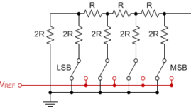
I would like to ask you if it is possible to use the 2-2R ladder for the gain setting to solve this problem and how to connect it in this InAmp

Thank you
Best Regards
 

I'd call it more of a binary weighted feedback network, but yeah. If you can stand some code-nonlinearity then parallel banks can be better than serial switched links, put the switches against gnd / outputs so their C is up against a low-Z source.
 
I'd call it more of a binary weighted feedback network, but yeah. If you can stand some code-nonlinearity then parallel banks can be better than serial switched links, put the switches against gnd / outputs so their C is up against a low-Z source.
Thank you freebird for your answer,
yes it doesn't matter me the code non-linearity,

It will be helpful to make me understand your explanation by referring to the basic r2r ladder below and how to connect it with regards to the inamp. I am working with single supply operation

Thank you
 

Attachments

  • r2r.png
    r2r.png
    5.5 KB · Views: 116

Dear Dana

Thank you very much for the resources you shared,

Actually, I am designing in the transistor level with CMOS technology. I also used digital pot in my design for the gain programmability, but as mentioned in my first post the number of the taps or switches will be equal to the number of gain setting I want to achieve.

for example if I have 16 gain level then I need 16 switches for each of R2, make them in total 32 switch. I have found out is affecting my AC performance.

Regardless this effect, and if I could use the r2r princible, I will achieve the 16 levels using only 4 switches. and if I use 6 bit r2r I will be able to chieve 64 gain level, making it the better programmable gain amplifier.

My problem is that to incorporate the r2r

Thanks
 

SPDT switches are generally used to illustrate the principle of R2R DAC. As you build a stand-in for switches it would be convenient if you can reduce parts count.
Since transistors conduct in one direction, you might get by giving each bit one switching device...
if you provide a reference voltage through adding another resistor. It's a workaround. Adjust reference voltage as desired.

My simulation has diodes conducting in one direction from each binary output (in order to depict a device which can source but not sink current). However if your R2R network can't be driven that way...
then you can substitute transistors and turn them On-Off via biasing signals from the bit wires. As an alternative reverse diode orientations so they point toward the binary outputs (in order to depict a device which can only sink current, not source current).

DAC 3 bit counter 3 diodes point away 8 resistors 1V reference.png
 
Hi,

May I ask what this "programmble gain" is used for.
In my many years of design I never needed that "high resolution" gain.

If we knew more about the signal source and where the signal goes to we maybe can give better assitance.

Klaus
 
R-2R ladder is specifically for a linear current-mode DAC
but that is not what you're building. Right?

You want a weighted ladder that gives you a "good enough"
outcome at the end of it all. Don't fixate on the form so early.
You don't care about code-linearity as long as you have the
step resolution across the span (which, worst-case bit bin size,
is maximized by dead linearity, but maybe 1 extra switch and
segment is better than trying more elaborate things).

Opportunistic things like turning a divider shunt R into a
parallalel shunt RDAC bank won't be easily linear, but can be
"plenty good enough" for next to no effort or risk.
 
Dear friends,

Thank you very much for your reply,

Beacause Klaus askem me about the application, I want to answer it here,

it is not for specific application rather than general purpose PGA. In my old design I have gain setting of

1,2,4,8,16,32,64,128

You know we amplify to fit the signal to the full-scale voltage of the ADC, so having more gain adjustment give me better control of the signal.

The r2r DAC can give me a finer step with fewer digital control switches/bits, but I am not sure in principle if I can use it as a voltage feedback attenuator to set the value of the feedback resistor and define the gain.

Thank you

Best Regards
 

Status
Not open for further replies.

Part and Inventory Search

Welcome to EDABoard.com

Sponsor

Back
Top