super
Full Member level 2
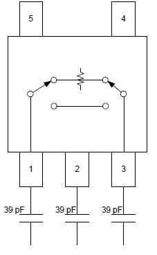
attenuator question..
Dear all :
In Attenuator circuit ,
1. why we need connect ground pin to capactor to ground ?
2. why we apply capacitor across MOS gate-drain ?
Thanks.
Dear all :
In Attenuator circuit ,
1. why we need connect ground pin to capactor to ground ?
2. why we apply capacitor across MOS gate-drain ?
Thanks.