Audioguru
Advanced Member level 7
- Joined
- Jan 19, 2008
- Messages
- 9,457
- Helped
- 2,151
- Reputation
- 4,302
- Reaction score
- 2,008
- Trophy points
- 1,393
- Location
- Toronto area of Canada
- Activity points
- 59,720
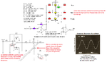
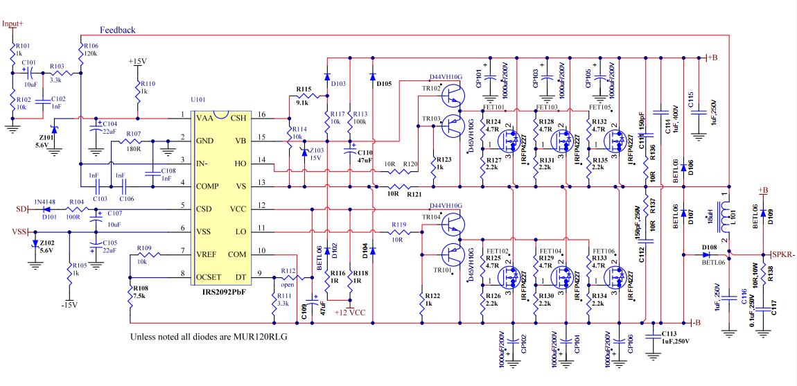
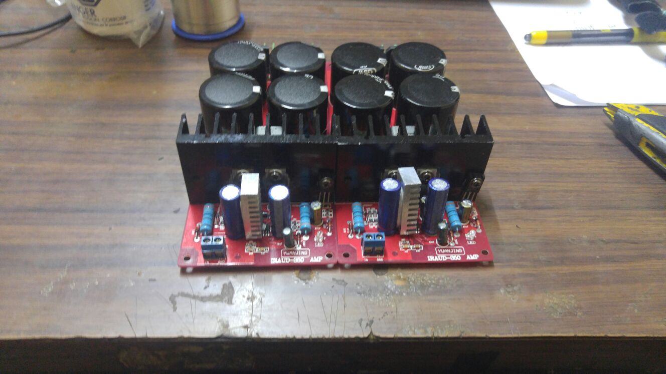
The amplifier is Chinese and they do not know how to say, "input impedance". It might be 14k ohms, then your volume control should be 7k ohms or less.
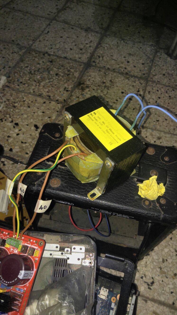
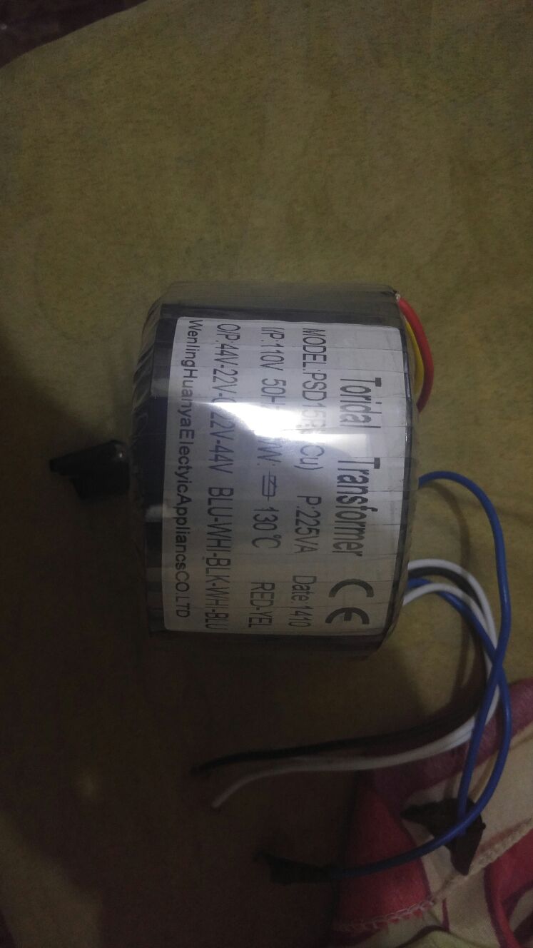
In your other thread about this amplifier I cannot remember what transformer you will power it with or what speaker you have.
In your other thread about this amplifier I cannot remember what transformer you will power it with or what speaker you have.