Continue to Site

Welcome to EDAboard.com

Welcome to our site! EDAboard.com is an international Electronics Discussion Forum focused on EDA software, circuits, schematics, books, theory, papers, asic, pld, 8051, DSP, Network, RF, Analog Design, PCB, Service Manuals... and a whole lot more! To participate you need to register. Registration is free. Click here to register now.

PWM Inverter for solar application

Status
Not open for further replies.
Mr tpetar, RAZA and ch wazir
If you do not understand something, it does not mean that it seems to be revolutionary, How to get 220 V from 12 V DC, what do you think ? I want to keep the answer for you but no problem, I will answer, A simple "BOOST CONVERTER" Mr. TPETAR, what do you think now?
I am wondering how do you talk about transformer in transformerless systems, (Transformerless means without transformer). this is a new technology so please be up to date.
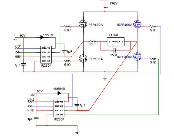
my question was how to drive MOSFETs, if you knew, I should be grateful if you answer otherwise you should keep your bad comments with you. the circuits you sent to me seem to be games or something very low level. In fact, inverters with NE555 are used in games for children, however, my project is to design a transformerless inverter 12/220 mounted directly to a photovoltaic panel. I am talking about micro-inverter, it is something like smart grid, novel technology. So please look at my question and forget the fact that my design is with transformer or with relay !!!!!!!
Kind Regards
YOUCEF2010
 

Dear tpetar,
Kind regards,
Is it possible you look at circuit number one (PIC16F877A) and tell me how to connect pulse transformer to drive the IGBTs of circuit 2. A simple "BOOST CONVERTER" Mr. TPETAR, what do you think now? In fact, inverters with NE555 are used in games for children, however, my project is to design a transformerless inverter 12/220 mounted directly to a photovoltaic panel. I am wondering how do you talk about transformer in transformerless systems, (Transformerless means without transformer). this is a new technology so please be up to date.

I think only one now, I wish you all luck in your project with revolutionar transformeless power inverter. You are very smart man and I hope you will become a great scientist soon. With this all World is Your.

Maybe next year You will get Nobel Prize for this.
 
Last edited:

Look at the schematics, 170V DC source is clearly shown. An hbridge is supposed to convert to 120V AC. Hbridge is driven by two half bridge driving ics. Four inputs are provided by digital ic, which is driven by microcontroller. So far so good. The problem is there is no ac output from hbridge. so it is suspected that it is not driven correctly. The discussion here is in wrong direction. When 170V is shown on schematics, is it necessary to know, how it is generated (with transformer or transformerless systems or boost converter or direct from batteries or solar panel or whatever) to awnser the problem? Do we have to show concern if it is for 50 or 60 Hz? Or if it is for 220V as in hbridge circuit in post #3.
The drive circuit in post #3 and hbridge circuit in post #11 makes a complete unit for ac sinewave generation. Generation of Hi voltage DC for driving hbridge is seperate issue, not aske for some problem. See double conversion topology.
Uninterruptible power supply - Wikipedia, the free encyclopedia
https://www.apcdistributors.com/whi... On-line vs. Line-interactive UPS designs.pdf
There is no pulse transformer is needed. Output of TC4469 directly connects to input of IR2304
 
Last edited:
Dera Mr tpetar,
The pulse transformer is a drive .it is not a step up or a step down transformer, please try to understant. yes it is a transformerless inverter for sine wave generation, 50 Hz, 12v DC as input. but the pulse transformer is to isolate the MOSFETs gates, we sometimes use optocoupler or some drives like IR2110.
Thank you very much for your wishes and if one day I get Noble prize, in that time I will not forget your help.
Only one thing please, if you are in this forum, it means you should respect people so that if you are skilled in something, you give the advice otherwise try to jump for an other.
Kindly
 

... it means you should respect people so that if you are skilled in something, you give the advice otherwise try to jump for an other.

the circuits you sent to me seem to be games or something very low level. In fact, inverters with NE555 are used in games for children, however, my project is to design a transformerless inverter 12/220 mounted directly to a photovoltaic panel.

Is this Your respect?
 

Mr. tpetar,
I am very sorry, you missunderstood me. I just want to tell you that inverters with NE555 are low power inverters so we cannot use them in advanced applications. once more, I am very sorry.
 

No need for sorry we are friends, I just try to help You with some circuits.
 

    V

    Points: 2
    Helpful Answer Positive Rating
It so confusing situation and Mr. Youcef is not willing to follow instead he is in teaching mode, so I quit right here from this post. I think we here for mutual interest and not for creating fuss. Sorry Mr. Youcef for any hurting post.
 

Mr RAZA, You do not have to quit, instead, I will quit. See, I asked if somebody knows how to drive MOSFETs with pulse transformer or optocoupler or any other drive, and I was waiting for any help. instead I have received your comments and their of Mr. tpetar. I think I have to quit. since you are older than me here so please stay, and I will quit. I am not in teaching mode but I am working on this fact more than one year so you can imagine the situation.
Once more, sorry and good luck in this respectful forum.
tarak salmi (youcef2010)
Ph.D student

---------- Post added at 19:12 ---------- Previous post was at 18:54 ----------

I dont think that he know what he do.

He whant revolutionar transformerless 12V to 220V :shock:

Mr RAZA, I know what I am doing, 170v DC as input to be boosted to about 350 V DC thraugh a boost converter. This 350v DC is enought to produce 220 V AC without transformer.
Yes, I come from Tunisia, the first revolutionar country, but my circuit is not revolutionar.
Please check this before you quit:
https://www.vincotech.com/fileadmin...orTransformerlessSolarInverter_PEE01-2010.pdf
 

Yes youcef, I know that is possible is without any doubts. But I was confused, as I said in my post from being 170 volts input and required 220 volts output, as the circuit was not clear that time as you did later on and I am a helping person by nature. When I felt the situation was going a bit harsh, I announced to quit the POST only not the forum. I may request you to continue on your project, Cheers :)
 

Dear Mr ALERTLINKS,
Thank you very much for your constractive help, However, still no one answered me, I do not have any problem with theory or simulation,
I will try to explain the problem,
See, in a full bridge, the MOSFETs are voltage controled (not like bipolar transistor which is current controled). since the MOSFETs are voltage controled, when you apply a PWM to the gate of the high side MOSFETs they will not switch, why ???? because the voltage must be measured between the mosfet gate and its source which must be grounded, but if you connect the source of such mosfet to the ground, no current will flow to the load.
Now I am using a micocontroler to generate PWM signals, then these PWM signals are introduced to an IC (TC4469CPD: please check page 4-269 in the datasheet: TC4469CPD pdf, TC4469CPD description, TC4469CPD datasheets, TC4469CPD view ::: ALLDATASHEET :::).
In that datasheet figure (Quad Driver for H-Bridge Motor Control), you will find motor but for my design, instead of this motor I will put one filter to get sinewave signal).
I realized all this circuit, unfortunately the mosfets did not switch and became very hot.
The question is also to mr. RAZA and Mr tpetar and all others that would like to do so.
Kind regards
Your's sincerely
Youcef
 

Mr DeepOne,
Yes, you are right, but since I could not do it, I stoped using the IR2110 and now I am using the TC4469CPD :) TC4469CPD pdf, TC4469CPD description, TC4469CPD datasheets, TC4469CPD view ::: ALLDATASHEET :::).
Thanks
 

>I am using the TC4469CPD<

Ok, but this schematics for working is required observance of some conditions
- using P&N type of mosfets
- supply voltage <20V.
 
Center point,where souce and drain meet should be connected to VS pin #6 (High voltage floating supply return) of relvant IR2304 IC.
44_1320914564.jpg

TC4469CPD can't drive high voltage like 170V. You need "level shifting" IR2110 and IR2304 has this built in requirement.
 
Last edited:
Mr. ALERTLINKS and Mr. DeepOne,
You are about to solve the problem, but please let me explain something:
In circuit_1, I have used PIC16F877A to generate PWM (8kHz) and two complimentary pulses (50Hz).
In the same circuit, these two complimentary pulses are multiplied by the PWM to generate the gate signals shown in circuit_2.
In circuit_3, the gate signals produced should be directly connected bto the corresponding gates (N-channel MASFETs).
This is in theory, it worked very well and all is right, unfortunately, when I passed to the practice, the control part is ok but the power stage (Inverter) did not work and the MOSFETs did not switch and became very hot.
Kind greetings


Dear Mr. Youcef2010 circuit_3 will work only with IR2110 or similar chips, not TC4469.
Apropos, 1N5818 is 1A 30V schottky rectifier, so it is not be able to work in such scheme.
 
Full bridge circuit needs two complimentary pairs of PWM signal to drive two half bridges. You have generated this signal using PIC16F877A. But you know it is only 5V peak. For driving half hbridge around 10V 1s needed for lower fet and Vcc+10V for upper Fet. In your case it is 170+10=180V. This voltage is generated by adding 10V to Vcc. An half bridge driver ic can do this.
Full bridge needs four seperate sinals for each fet. In your schematic tc4469 generates these four signals but it can not drive directly full bridge all four fets n-channel. So here bridge driver is needed such as ir2110 or ir2304. Out puts of tc4469 can drive inputs of ir2110 or ir2304. If you draw complete schematic of driver and output stage with interconnections and pulsed at each point, then we can discuss further what is going on.
 
Dear Mr. ALERTLINKS,
I agree with you 100%. In fact after the TC4469, I have added two IR2110 and all is ok. Now I have got all the control signals for the four MOSFETs but the problem now is when I try to supply the inverter with 30v DC (for example) I get only 10v at the inverter output. I did not put heatsinks for the MOSFETs, so maybe the heat limits this output ! do you think so? what is the influence of heat on the inverter? Please reply.
 

Status
Not open for further replies.

Similar threads

Part and Inventory Search

Welcome to EDABoard.com

Sponsor

Back
Top