Continue to Site

Welcome to EDAboard.com

Welcome to our site! EDAboard.com is an international Electronics Discussion Forum focused on EDA software, circuits, schematics, books, theory, papers, asic, pld, 8051, DSP, Network, RF, Analog Design, PCB, Service Manuals... and a whole lot more! To participate you need to register. Registration is free. Click here to register now.

PWM and MOSFET problem ?

Status
Not open for further replies.
Hi,
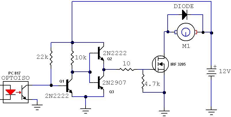
I understand you are using n-channel MOSFET. In original schematics gate voltage range is ~11V - 12V dependng from optocoupler. However Vgs(th) of the FET is +3V. Therefore the MOSFET's working point located in saturation area every time. From my opinion you'd better to use p-channel MOSFET instead or change gate voltage range. In next revision of the circuit you are using PNP and NPN pair to manage MOSFET gate voltage. This additional circuit capable switch MOSFET on/off and as result solve the problem.

Added after 3 minutes:

About diode I agree you have to use fast diode to depress positive spike and preserve MOSFET from damage

Added after 1 minutes:

It's not enough technological diode inside MOSFET
 

Therefore the MOSFET's working point located in saturation area every time.
That's good. It's a switch, so saturation is highly desirable.

do i need a diode in reverse biase across motor to kill inductive kicks?? as MOSFET has builtin Diode
Sure you need. Look sharp! MOSFET reverse diode is conducing with negative drain voltage while the freewheeling diode conducts with positive drain voltage above supply, simply opposite.

To say it suppresses spikes misses the circuits operation principle. A PWM drive tries to achieve a continuous motor current (with some ripple). The PWM is intended as a buck converter with the armature inductance as energy storage.
 

That's good. It's a switch, so saturation is highly desirable.
Sure. However the MOSFET every time in on state. This mode is amplifier mode rather than switch.
To say it suppresses spikes misses the circuits operation principle. A PWM drive tries to achieve a continuous motor current (with some ripple). The PWM is intended as a buck converter with the armature inductance as energy storage.
Sure. This is main principle of PWM. But diode function is protect MOSFET during fast changes current through inductance
 

So you mean, that the MOSFET doesn't turn off in the orginal circuit? I think, it turns off, but too slowly. This isn't particularly a problem of threshold voltage rather than a too high driver impedance.

But diode function is protect MOSFET during fast changes current through inductance.
The diode also protects the MOSFET. But that's not it's primary function. The primary function is to allow the stored energy in armature inductance to drive the motor. The circuit looks like an usual protection circuit, but in PWM operation, it has a different purpose. The MOSFET is already protected by it's built-in zener diode. By utilizing this protection method, the stored energy is generating losses at the transistor instead of driving the motor.
 

However Vgs doesn't drop less than ~11V. It's not clear how it off at all.
 

hameeds01 said:
now its working fine ..........

do i need a diode in reverse biase across motor to kill inductive kicks?? as MOSFET has builtin Diode ..........

Hameeds01....Are you sure your driver circuit provided here is working?. I doubt the 2N3907, a PNP, can be turned ON in this configuration.
 

However Vgs doesn't drop less than ~11V.
Where did you get this idea? When the octocoupler isn't driven, it falls to 0.

Hameeds01....Are you sure your driver circuit provided here is working?. I doubt the 2N3907, a PNP, can be turned ON in this configuration.
You right, emitter and collector are mixed up. The push-pull circuit from the quoted thread is showing it correct. There are many ways to confuse even a simple circuit.
 

guys
After adding the diode across the motor terminals now the motor is running very smooth, quiet & no whistling sound, now it is making good use of the stored energy in the Armature of the motor during the Off time.
At the moment I m using ordinary 1A Diode tomorrow I will change it with 10A (FEP16CT) high speed diode soon.
The Push-Pull driver is working absolutely fine, no more heating problem even @ the load of 25A.(tested)

@ stanislavb


When the Q2 2N2222 (NPN) is in a forward biased condition the Vgs = 12v
& When the Q3 2N2907 (PNP) is in a forward biased condition the Vgs = 0v
at a time only one can be in a forward biased condition, when the opto coupler is in ON state only Q2 will conduct , & when the opto coupler is in OFF state Q1 & Q3 both will conduct….
 

Hameed u can also shorten your circuit...Use a power mosfet driver instead of transistors...u can use series gate resistor of 10ohm to protect mosfet from HF ringing..
 

hello frnz
i am doing a project named-
induction motor drive using pwm control
can any one help me in this project as i am not able to figure out what exactly to do.
which pwm control ckt to use.
 

Nobody thought about applying negative voltage on the gate? Someone would have any circuit for that?
 

i am using the induction motor
of normal rating i.e like a switched reluctance motor
actually i am being told to simulate a circuit using orcad or picepiece which can give the pluses to the motor for its function....and by varying the same to control the motors speed
i hav to make the ckt. for any ratings in the begining ...then my mentor il specify the exact rating of motors to be used.
plz help meeeeeeeeeee.....

Added after 4 minutes:

also the ckt to be simulated has to be of a pwm controler.
plz help me find the simulation codes to make a pwm controler(inverter) which can be used to regulate the speed of the motors
 

Try using a 555 as your PWM, alos I think you should configure your opto-coupler and the transistor in a darlington way, because the saturation voltage of the opto may be to high so the 2n2222 would not turn-off completly. I like to start over in a different way when it is not working!
 

hello,
the ckt i am designing is of VVVF control.
frm this i have to operate a slip ring type induction motor.
i am not being able to design a pwm control for the inverter.
also i need the output to be around 220volts,but a am getting 150 volts only as output...
pls help!!!!!!!!!!!!!!

Added after 2 minutes:

i am using the 555 timer but what to give it in triggring pulse??
 

I would use an optocoupler like the hcpl2201 with a bipolar push-pull stage after it to deliver enough current to turn the mosfet on and off quickly enough.
Your problem there is a very slow turn off time.
 

my project is using buck converter,the problem it is i don't know how to switch on or off the mosfet (IRF150) with variable input voltage (13V to 24V).for this buck,my o/p is constant which is 12V with variable input voltage.can any1 help me on how to solve this prob ??
 

Status
Not open for further replies.

Part and Inventory Search

Welcome to EDABoard.com

Sponsor

Back
Top