Continue to Site

Welcome to EDAboard.com

Welcome to our site! EDAboard.com is an international Electronics Discussion Forum focused on EDA software, circuits, schematics, books, theory, papers, asic, pld, 8051, DSP, Network, RF, Analog Design, PCB, Service Manuals... and a whole lot more! To participate you need to register. Registration is free. Click here to register now.

pulse Width

alishbah Shafique

Newbie level 4
Joined
Jul 30, 2023
Messages
6
Helped
0
Reputation
0
Reaction score
0
Trophy points
1
Activity points
28
how can we find pulse width of output signal in Simulink. which model we use to extract pulse width
 
* Can you read pulse length by examining time markers, or scope traces which contain time markers ?

* You may need to set up a faster clock in the same circuit layout, and see how high it counts during the pulse. You must contrive a way to turn the clock on and off.
 
i want to find pulse width of below given pulse .like time of arrival and time of departure .but don't know the exact methodology...
 

Attachments

  • WhatsApp Image 2023-07-30 at 05.22.22.jpeg
    WhatsApp Image 2023-07-30 at 05.22.22.jpeg
    48.2 KB · Views: 66
* Can you read pulse length by examining time markers, or scope traces which contain time markers ?

* You may need to set up a faster clock in the same circuit layout, and see how high it counts during the pulse. You must contrive a way to turn the clock on and off.
 

Attachments

  • WhatsApp Image 2023-07-30 at 05.22.22.jpeg
    WhatsApp Image 2023-07-30 at 05.22.22.jpeg
    48.2 KB · Views: 65
I suppose your red marker is the pulse length you wish to measure? The scope shows it occupies 5 clock cycles.

To measure its duration with electronic devices... There's the popular 4017 decade counter IC. Your simulator may contain the model.

You must contrive methods to:
* reset the count
* start the count
* apply correct voltage to the Count Enable pin.

I had to experiment with my simulation to get the desired led to light and stay on as the pulse ends. Notice the fifth led is on, telling us the pulse lasted for 5 clock cycles. I had to install an invert-gate to apply the proper polarity to make the 4017 advance.

4017 IC advances count for each clock pulse lights led.png
 
Last edited:
I suppose your red marker is the pulse length you wish to measure? The scope shows it occupies 5 clock cycles.

To measure its duration with electronic devices... There's the popular 4017 decade counter IC. Your simulator may contain the model.

You must contrive methods to:
* reset the count
* start the count
* apply correct voltage to the Count Enable pin.

I had to experiment with my simulation to get the desired led to light and stay on as the pulse ends. Notice the fifth led is on, telling us the pulse lasted for 5 clock cycles. I had to install an invert-gate to apply the proper polarity to make the 4017 advance.

View attachment 184162
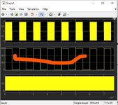
no suppose its a radar received signal and i want t extract certain parameters of this signal .like freq ,pulse width .so how can i find the pulse width of single pulse in simulink. which block should i use
 
take it as example
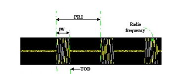
You should first ask how to detect radar pulse then ask how to do that in your platform (such as Simulink). I can answer the first question:
To detect a radar pulse you correlate your received pulse tone with a template of same (also called matched filter). You get a peak. Then you proceed to find the length between two peaks.

As to Simulink blocks that is for you to choose from their library. Many people never use Simulink.
 

LaTeX Commands Quick-Menu:

Similar threads

Part and Inventory Search

Welcome to EDABoard.com

Sponsor

Back
Top