ln30356
Newbie level 4
Hello everyone,
I have a problem about simulation in proteus, and I ask for everyone's help, please
My problem is as follows:
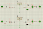
In proteus, I simulate a simple source circuit 7805 (as figure attached),
For the first circuit (above circuit), the simulation is ok. I also copied the first circuit to get the second circuit (circuit below in figure), but it doesn't work. In the circuit below, the output current of IC 7805 is 0, the output voltage is 5V (as supposed), the LED is not illuminated. I do not understand why two completely identical circuit (because I used block copy in proteus) does not work the same.
I attached the figure and schematic file below.
I'm using Proteus 8.3
Hope I can get answers from you guys, thanks.
P/S: sorry for my English
View attachment DC5V.rar
