Continue to Site

Welcome to EDAboard.com

Welcome to our site! EDAboard.com is an international Electronics Discussion Forum focused on EDA software, circuits, schematics, books, theory, papers, asic, pld, 8051, DSP, Network, RF, Analog Design, PCB, Service Manuals... and a whole lot more! To participate you need to register. Registration is free. Click here to register now.

Protecting FETs from CEMF spikes

Status
Not open for further replies.

Kerrowman

Member level 4
Joined
Oct 12, 2021
Messages
75
Helped
0
Reputation
0
Reaction score
2
Trophy points
8
Location
West Penwith
Activity points
578
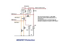
In my doing some research into the effects of HV CEMF pulses on batteries, I am finding that my MOSFETs understandably get easily damaged by these pulses, even when I have tried to isolate and protect them using a pair of chokes (see pic).

I also attach the relevant part of the circuit and wondered if anyone had any straightforward ideas as to how to block the CEMF pulses (~ 1,200V) from reaching the FETs? Maybe a fast diode between the Drain and Source of each one? However, the Source does not connect to Ground but supplies another part of the circuit.

Thanks
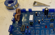
Chokes.jpg

FET Protection.jpeg
 

The chokes may actually be making things worse. CEMF by definition is of reverse polarity so the first thing to try is simply diodes across the batteries, wired so normally not conducting of course. I would suggest fast Schottky diodes rated at 1A or more. You may find it best to physically connect them to the wires "pulse 1" and "pulse 2" rather than across the battery terminals to reduce the CEMF path length to ground, you want to trap the pulse at the earliest opportunity as it reaches the circuit.

Brian.
 

Thanks but won’t diodes across the batteries absorb the spikes and prevent them fully entering the batteries? I want the spikes but just not interfering with the FETs. I’m not trying to remove them as perhaps most circuits would like.
 

Maybe my understanding of what you want to achieve is wrong. Are you saying you want the pulses to charge the batteries or is something else charging them and the pulses are superimposed on the voltage? Ordinarily, the battery itself would be able to absorb any voltage higher than terminal voltage by sinking more current into itself. Surely you are not trying to charge 12V batteries with 1.2KV pulses.

Regardless, the polarity should not reverse or the batteries and connected devices could be damaged. Adding reverse connected diodes will only clamp voltages which are the opposite polarity to the batteries themselves. They will not conduct at all if the voltage remains the right way around.

Brian.
 

As I state in my first post I’m researching the effect on the batteries of the HV pulses (not going into the Physics behind that here) so I don’t want to dissipate them but rather stop them interfering with the two FETs that are also connected to the + terminal of each battery.

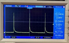
My thinking behind the chokes is that they should offer a high attenuation to the fast (20us) rise times of the pulses but little to the DC from the battery. Perhaps a choke with more turns and finer wire would be better at filtering them?
 

Hi,

I don't understand the whole circuit ... and the description.
I see 5 "open" signals in your schematic. Where do they come from or go to?
What's the signal waveform, timing, polarity? Description?
What do you want to achieve?

You write you want the 1200V pulses across the 12V batteries. (At least this is what I understand)
But indeed I doubt this useful at all.

Klaus
 

I don't understand it either.

But as a solution, you could use avalanche rated mosfets, or transient suppression (TVS) devices connected source to drain. Either will go into momentary conduction and clamp the voltage to a safe level.
 

... and the problem with the chokes is if they 'absorb' a fast current pulse it has to go somewhere. It will release with reversed polarity when the pulse ends. It might add to the problem rather than solve it.

Adding TVS across the MOSFETS may protect them but the pulse would then pass to the "another circuit".

I designed and built a 300A pulse battery charger for 'C' size NiCads for a special purpose a long time ago but I've never heard of pulse voltages being used, at least not ones above normal charging voltage.

Brian.
 

I think you forgot to mention what the purpose of the FETs is, and how their gate voltages are controlled. If they're meant to function as simple switches, then Vds breakdown shouldn't be a problem, but maybe Vgs could be exceeded, in which case isolated gate drive circuits would help.
 

I attach a pic of the CEMF pulses measured with a 10:1 voltage divider.

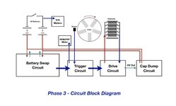
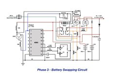
The purpose of the two FETs is to periodically switch which battery is providing power to the rest of the circuit and which is being ‘hit’ with the HV pulses so their gates are fed from the two batteries by a latching relay operated by a 4060 based timer. These components are all part of the ‘battery swapper’.

When I have added the high sided switched ‘Cap Dump’ circuit that I’m assembling then the batteries will be delivered with low voltage, high current discharges to charge them so this is an intermediate stage for comparison. Even in this configuration the battery voltages does rise as the internal chemistry responds to these HV spikes that carry almost no current.

I attach a schematic to give the larger picture and where the HV transients are produced by the main FET in the Drive circuit and which is protected by a DSEI 12 (FRED) diode.

The chokes have worked before but having added a driver for the main FET, the transients have risen from 500-1200V which is good as a whole but more troublesome for those two FETs. I did wonder about putting some device across them but reasoned that doing so would neutralise the spike in a way that would prevent it from reaching the battery since in effect the drain and the + battery terminal are connected. That’s why I was going for a ‘blocking’ technique in that branch rather than an ‘absorbing/neutralising’ approach.

I could try one across the drain-source, or perhaps drain to ground, and see what happens.

Are avalanche fets just beefier and more resistant to transients than others?
--- Updated ---

. . . and here is the full swapper circuit.
 

Attachments

  • 7B42D0E1-22C4-467D-943A-94CC7404972C.jpeg
    7B42D0E1-22C4-467D-943A-94CC7404972C.jpeg
    1.4 MB · Views: 89
  • 41EC960B-765D-4FC5-819C-094DF9B0D918.jpeg
    41EC960B-765D-4FC5-819C-094DF9B0D918.jpeg
    185.6 KB · Views: 101
  • 306555B9-03FF-4345-9BE4-9E034E2342DD.jpeg
    306555B9-03FF-4345-9BE4-9E034E2342DD.jpeg
    224.2 KB · Views: 115
Last edited:

I have serious reservations about that circuit!. Are you really powering the relay coils through 18K resistors and expecting the 4060 to sink the coil current? I wonder if the relay is only partially operating or maybe the back spike from the coil is causing your damage. Even if it a latching relay, the initial current has to come from the IC.

Why are these high voltage spikes generated, what mechanism creates them?

Brian.
 

The 4060 is just providing a timing pulse for the relay to flip over. I have explained in some detail how the transients are created in post#10
 

Did you ever observe 1200V pulses while the generator is loaded with a battery? I'd expect the battery to effectively short the pulse and limit the peak voltage to a few 10 V. Exact voltage level depends on battery wiring as the dominant source of series inductance and generator current capability. Presuming the generator coil current isn't higher than a few A, the back-EMF current can't rise above this value.

The most likely way to damage a FET in your setup is to switch the swap circuit just during a pulse and lead part of the high voltage pulse to a gate due to relay arcing. At this moment, the pulse generator is already disconnected from one battery and not yet shorted by the other. This will happen from time to time as the swap timer is apparently free running, not synchronized with the generator.
 

Are avalanche fets just beefier and more resistant to transients than others?
Common garden variety mosfets have a maximum voltage rating, if exceeded the device breaks down destructively almost always to a permanent dead shorted condition.

Avalanche rated mosfets go into a non destructive high dissipation mode, rather like a zener diode. The voltage is clamped, and provided the energy is not enough to melt the junction, it will survive. This works quite well for very short duration spikes, especially if they are non repetitive.

The data sheet for the specific mosfet will tell you if its an avalanche rated device.
Here is a good explanation by a Texas Instruments engineer:
https://training.ti.com/understanding-mosfet-datasheets-avalanche-ratings?cu=894015
 

Yes when the spikes meet the battery they are no longer measurable. The suggestion that it’s the relay cross over that brings the problem sounds very feasible and so I guess using avalanche rated devices would help with that.

Thanks for the suggestions. 😊
 

Some additional hints about purpose of the apparateous and design details can be found in previous threads
--- Updated ---

Yes when the spikes meet the battery they are no longer measurable. The suggestion that it’s the relay cross over that brings the problem sounds very feasible and so I guess using avalanche rated devices would help with that.
Thanks for confirming my assumption about battery voltage. This also suggests that the FETs are killed by gate overvoltage, due to parasitic effects of the swap relay circuit. TVS diodes across gate-source terminals should be sufficient to avoid this specific problem, not talking about other possible circuit issues or general usefulness.
--- Updated ---

I notice, that a relay between drain and gate doesn't turn the FET fully on, respectively causes several V voltage drop between battery and output voltage. You original transistor-less circuit is much better in this regard https://www.edaboard.com/attachments/generator-circuit-jpg.172393/
 
Last edited:

May I suggest a more robust and simpler approach is to move the FETs to the low side of the battery and switch the negative ends instead of positive. Grounding the source pins will let the 4060 and an inverter drive the gates directly without a relay and if necessary (which I doubt) it becomes much easier to clamp the drain voltages to ground. In fact if this is supposed to present high voltage spikes to the batteries, a Zener diode across D-S rated just above battery voltage will still let the spikes reach them.

Brian.
 

All sounds possible however I already have the circuit built and the swapper has worked ok for 3 years. It’s the ramping up of the HV transients using the FET driver that I think has made the relay crossover issue reach a critical level for FET survival.

I have made the PCB with pull out sockets for the FETs so I can just plug in and try some avalanche sturdy ones but are their gates more resistant or is it their drains and sources? It seems my Gates are at most risk of damage.

I can’t remember why I moved away from a relay based version. It might have been simple due to part availability.

The use of Zener diodes across the D-S sounds an option. Is that Cathode to Drain? But if the issue is Gate over voltage via the relay then a Zener will not impact that surely?
--- Updated ---

Some additional hints about purpose of the apparateous and design details can be found in previous threads
https://www.edaboard.com/threads/fet-driver-design.399904 https://www.edaboard.com/threads/extracting-energy-from-a-rotor.400541
Yes these are my posts 😊

Regarding using a TVS diode across the Gate-Source of the two FETs, would these be the unidirectional or bidirectional variety?
 
Last edited:

Simply work out what level of spike the mosfets can withstand and put a zener + diode across each choke to limit the spike to this level, e.g. 1N5407 & 75V 5W zener to limit to ~ 100 Vpk

47V 5W zener will limit to ~ 60V peak

you can use 2 x zeners toe to toe as well ( i.e. inverse series ) to clamp spikes both ways ....
 

Yes I can see that would work but the IN5407 is a regular power diode and not a Zener. Or the other option is to use a 12V TVS across the Gate and Source of each FET as previously suggested.

I’m not sure where I would find data on what spike voltage a FET could withstand. I don’t recall seeing such info on data sheets so there would be some guesswork.
 

Status
Not open for further replies.

Similar threads

Part and Inventory Search

Welcome to EDABoard.com

Sponsor

Back
Top