mahmood.n
Member level 5

We have a DE0 board and the manual is quite straight forward. Consider this simple counter code
According to the manual, the push button pins are described in page 27 fig 4-5
F1 -> CLK
G3 -> RST
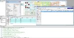
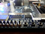
And the LEDs are described in page 28, fig 4-8 (J1, J2, J3, H1, F2). I configured the chip with these pins. As you can see in the attached picture, the programming phase is done successfully and I see that board initial works (flashing leds) are stopped for programming. However, as I press the buttons, the LEDs don't work. If you look at the attached board picture, the five bits (output q) are turned off which shows the board is configured.
Any idea to debug more?
Code:
library ieee;
use ieee.std_logic_1164.all;

entity counter2 is
	port( clk, rst: in std_logic;
		  q: out integer range 0 to 31);
end;

architecture x of counter2 is
begin
	process( clk, rst )
		variable tmp: integer := 0;
	begin
		if ( rst = '1' ) then
			tmp := 0;
		elsif (clk'event and clk = '1') then
			tmp := tmp + 1;
			if ( tmp = 32 ) then
				tmp := 0;
			end if;
		end if;
		q <= tmp;
	end process;
end;
According to the manual, the push button pins are described in page 27 fig 4-5
F1 -> CLK
G3 -> RST
And the LEDs are described in page 28, fig 4-8 (J1, J2, J3, H1, F2). I configured the chip with these pins. As you can see in the attached picture, the programming phase is done successfully and I see that board initial works (flashing leds) are stopped for programming. However, as I press the buttons, the LEDs don't work. If you look at the attached board picture, the five bits (output q) are turned off which shows the board is configured.
Any idea to debug more?