Continue to Site

Welcome to EDAboard.com

Welcome to our site! EDAboard.com is an international Electronics Discussion Forum focused on EDA software, circuits, schematics, books, theory, papers, asic, pld, 8051, DSP, Network, RF, Analog Design, PCB, Service Manuals... and a whole lot more! To participate you need to register. Registration is free. Click here to register now.

Problem with clk jitters in a 1/4 divider

Status
Not open for further replies.

jason_tian

Junior Member level 2
Joined
Jan 8, 2007
Messages
20
Helped
1
Reputation
2
Reaction score
1
Trophy points
1,283
Activity points
1,389
Hi,everyone
I'd like to make a 1/4 devider ('osc'/40KHz---->'clk'/10KHz) by the code as follows:

reg[9:1] devider;
always @(posedge osc)
if(devider>=2) begin clk<=~clk;devider<=1;end
else devider<=devider+1;

the waveform of 'clk' jitters, sometimes the 'clk' raises or falls on a wrong edge of 'osc'.please refer to the picture.
EPM240T is used.

Added after 3 minutes:
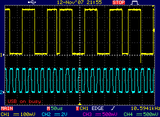
82_1194876265.gif
[/img]
 

devider jitters

simulation in Q2 is ok, why the practical waveform varies?
 

devider jitters

I'm not familiar with that particular CPLD, but your hardware may have a signal integrity problem, such as ringing on the osc input, ground bounce, insufficient power supply decoupling capacitors, or something like that. Such problems occur within a few nanoseconds, so you'll need to speed up your scope's sweep speed.

By the way, you can create a divide-by-4 by clocking a simple two-bit counter, and outputting the most-significant bit.
 

devider jitters

Hi echo47,
thanks! I'll check the 'osc' signal.
and do you think there a signal integrity problem within the CPLD due to bad decoupling of power supply?
 

devider jitters

My first guess is ringing on the osc signal, although insufficient power supply decoupling can also cause strange flip-flop behavior.
Here's a section from the MAX II handbook giving some guidelines for PCB layout and power supply decoupling. Maybe it will help you find the problem.
**broken link removed**
 

    jason_tian

    Points: 2
    Helpful Answer Positive Rating
Re: devider jitters

Hi echo47,
I checked the waveform of 'osc' in nanoseconds but found it's smooth. then I added another test signal 'tclk' as:
.....
reg[2:1] devider;
always @(posedge osc)
begin tclk<=~tclk;
if(devider>=2) begin clk<=~clk;devider<=1;end//osc/bclk=40k/5k=8.
else devider<=devider+1;
end
.....
the dubious waveform I got from the oscillagraph is attached here:

According to the area around the red line,I wonder if there's something wrong within the CPLD,because 'clk' and 'tclk' don't match.

regards!
 

devider jitters

tclk should simply toggle, but instead it's doing weird things. This still feels like some sort of signal integrity problem, but I suppose a defective part could cause weird behavior too.

Is this a commercial PC board, or your own fabrication?
 

    jason_tian

    Points: 2
    Helpful Answer Positive Rating
Re: devider jitters

Hi echo47,
thanks!
It's really a signal integrity problem!
I disabled my oscillator of 'osc' and feed in with a SG,then, all things go all right. my oscillator is made of CMOS invertors. the wave is smooth on the oscilligraph(BW=200M,SR=1G) because I used shunt-cap at 'osc' node but still has phase-jitter. maybe this phase jitter caused weird behavior ? as long as I added a 220p shunt cap at a mid node of the cascade inverters,the mulfunction was reduced a lot.
if it is, but how can a phase jitter cause that behavior?
It's a commercial PC board.
 

devider jitters

Great that you are close to finding the problem.

Phase jitter should be harmless.

Your chain of inverters oscillates at 40 kHz? Be sure the rise/fall times are sufficiently fast for the CPLD. If too slow, the CPLD input buffer can oscillate during the transition.
 

    jason_tian

    Points: 2
    Helpful Answer Positive Rating
devider jitters

yes, maybe the rise/fall edges are too slow,for I shunt a 220p cap! thanks a lot echo47! I'll check it later and report the result.
 

Re: devider jitters

Hi,
the jitter is got rid of as I removed the shunt cap to make the rise/fall edge sharp.
thanks again!
 

Status
Not open for further replies.

Part and Inventory Search

Welcome to EDABoard.com

Sponsor

Back
Top