Continue to Site

Welcome to EDAboard.com

Welcome to our site! EDAboard.com is an international Electronics Discussion Forum focused on EDA software, circuits, schematics, books, theory, papers, asic, pld, 8051, DSP, Network, RF, Analog Design, PCB, Service Manuals... and a whole lot more! To participate you need to register. Registration is free. Click here to register now.

problem in PIC16f877a (hardware)

Status
Not open for further replies.

toto_na16

Member level 1
Joined
Feb 21, 2010
Messages
34
Helped
1
Reputation
2
Reaction score
0
Trophy points
1,286
Location
Egypt
Activity points
1,478
hi all ,

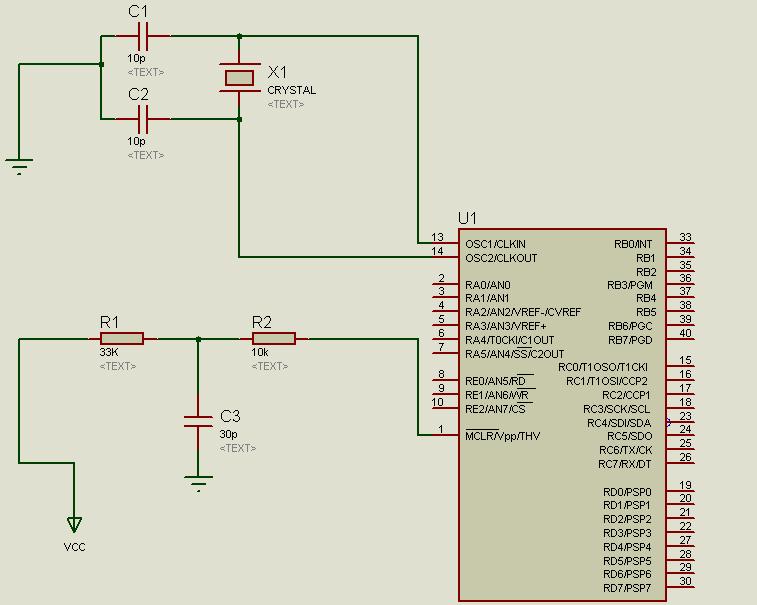
I recently bought a MCU (PIC16f877a) and connected it as the circuit below and connecting leg 11 to 5V and 12 to GND

and the crystal used 16 MHZ

when programming using winpic I choose no WDT and HS oscillator


but the circuit doesn't respond to anything and the LEDs don't lit up .


the program I used to test if the unit is working :D


Code:
void main(){
     TRISD = 0x00;
     TRISC = 0x00;
     TRISA = 0x00;
     TRISB = 0x00;
     PORTD = 0xff;
     PORTC = 0xff;
     PORTA = 0xff;
     PORTB = 0xff;

     }


SO if you please could help me in this serious problem and I will be thankful


Regards
 

1. there are no LEDs in the schematic !
2. Short out R1 and remove C3, they do nothing at all.
3. You MUST fit decoupling capacitors across 5V and Ground. I suggest 10uF and 100nF in parallel.
4. What does your software do when it finishes the program? Try wrapping the code inside the main function in a "while(1)" loop so it repeats rather than falling off the end of the code.

Also make sure the wiring to the crystal is as short as possible and the ground side of C1/C2 is a short connection to the processor ground too.

Brian.
 

betwixt said:
1. there are no LEDs in the schematic !
2. Short out R1 and remove C3, they do nothing at all.
3. You MUST fit decoupling capacitors across 5V and Ground. I suggest 10uF and 100nF in parallel.
4. What does your software do when it finishes the program? Try wrapping the code inside the main function in a "while(1)" loop so it repeats rather than falling off the end of the code.

Also make sure the wiring to the crystal is as short as possible and the ground side of C1/C2 is a short connection to the processor ground too.

Brian.

i don't understand the point number 3 and 5


thank you for your help
 

Please post the complete schematic with the LEDs and your power and ground pins. Otherwise it is impossible to determine what the problem is.
 

here is the schematic for the circuit

thank you all
 

You dont show pins 11,12,31 and 32 are they connected?
 

aj9999 said:
You dont show pins 11,12,31 and 32 are they connected?

these pins aren't existed in ISIS

but in the real board

i connected Vdd to 5V 11-32
and Vss to Gnd 12-31

thank u
 

It is best to show those pins, if you choose not to show Vss and Vdd on the part you should at least show the capacitors that you have between pwr and gnd close to the part so that people know you have them. If you dont have those capacitors you need to add them. Also did you add the while() loop as betwixt suggested?
 

aj9999 said:
It is best to show those pins, if you choose not to show Vss and Vdd on the part you should at least show the capacitors that you have between pwr and gnd close to the part so that people know you have them. If you dont have those capacitors you need to add them. Also did you add the while() loop as betwixt suggested?

I added the while () loop

where to add capacitor and what value ?

and should I connect all pins 11,12,31,32 or pins 11,12 only ?
 

Add a 10uF and a 0.1uF cap , place them betweeen Vdd and Vss. Place it physically close to the PIC. You can tie the 2 pwrs and 2 grounds together.

You might want to increase the xTal caps from 10pf to the standard 22pf. Make sure it is very close to the PIC and that the wires/traces are as short s possible.

Please post the updated schematic with these changes to ensure we are all understanding what you have and also post your complete code with the while loop and your include and config statements.
 

aj9999 said:
Add a 10uF and a 0.1uF cap , place them betweeen Vdd and Vss. Place it physically close to the PIC. You can tie the 2 pwrs and 2 grounds together.

You might want to increase the xTal caps from 10pf to the standard 22pf. Make sure it is very close to the PIC and that the wires/traces are as short s possible.

Please post the updated schematic with these changes to ensure we are all understanding what you have and also post your complete code with the while loop and your include and config statements.


Code:
void main(){
     TRISD = 0x00;
     TRISC = 0x00;
     TRISA = 0x00;
     TRISB = 0x00;

     while(1){
     PORTD = 0xff;
     PORTC = 0xff;
     PORTA = 0xff;
     PORTB = 0xff;
     }

     }
I'm using mikroc so the include doesn't existed but I have to choose the device and I have choosen PIC16F877A
 

Ummmm.....

The capacitors go in parallel not series!!

The idea is they ensure there is no signal across the supply lines, only the 5V DC needed to power the micro. Without them, you will get noise across the supply and the internal oscillator will probably fail to start up, or at best it would be erratic.

You can safely drop R2 to 1KΩ, it's present value will make the LED very dim.

And... you must connect all VSS and VDD pins.

Brian.
 

After you make the changes betwixt suggested , check that you have the WDT,BOREN both turned off. Maybe even make sure that SSPCON1 is set to zero to disable the SPI port, although it should start up with it disabled.

Have you checked the Vss and Vdd pins at the uC with a multimeter or oscope to ensure that the device is getting power, then have you checked that the LED pin is not changing its value,check it with a DMM or oscope not just with the LED, also check the other port pins.

Next how do you know the part is programmed and not defective, try a different PIC or try your PIC in a different demo board. Check the crystal, they are easily damaged, maybe even go with a slower one until you get everything else working. Generally the higher speed crystals are more susceptable to trace/wire resitance and capacitance than a lower speed ones.

Alex
 

betwixt said:
Ummmm.....

The capacitors go in parallel not series!!

The idea is they ensure there is no signal across the supply lines, only the 5V DC needed to power the micro. Without them, you will get noise across the supply and the internal oscillator will probably fail to start up, or at best it would be erratic.

You can safely drop R2 to 1KΩ, it's present value will make the LED very dim.

And... you must connect all VSS and VDD pins.

Brian.

ok thank you

Added after 7 minutes:

aj9999 said:
After you make the changes betwixt suggested , check that you have the WDT,BOREN both turned off. Maybe even make sure that SSPCON1 is set to zero to disable the SPI port, although it should start up with it disabled.

Have you checked the Vss and Vdd pins at the uC with a multimeter or oscope to ensure that the device is getting power, then have you checked that the LED pin is not changing its value,check it with a DMM or oscope not just with the LED, also check the other port pins.

Next how do you know the part is programmed and not defective, try a different PIC or try your PIC in a different demo board. Check the crystal, they are easily damaged, maybe even go with a slower one until you get everything else working. Generally the higher speed crystals are more susceptable to trace/wire resitance and capacitance than a lower speed ones.

Alex


I have 3 PICs that are old

so I bought new one but it also not working

and I bought two new crystals

I wish to ask also about PWRTEN
 

if u are using ISIs for the circuit simulation then no need to show the VCC & Gnd pins they are taken care of . now about the schematics connect the MLCR pin to +5v, connect 330ohms resistr to led then ground,

the program should be

#include"16f877A.h"
# use delay(clock=16000000)

main()
{

top :eek:utput_c(0x00);
delay_ms(100);
output_c(0xff)
goto top;

}
 

nikhil_damle said:
if u are using ISIs for the circuit simulation then no need to show the VCC & Gnd pins they are taken care of . now about the schematics connect the MLCR pin to +5v, connect 330ohms resistr to led then ground,

the program should be

#include"16f877A.h"
# use delay(clock=16000000)

main()
{

top :eek:utput_c(0x00);
delay_ms(100);
output_c(0xff)
goto top;

}

your code is giving errors in # directives

I'm using Mikroc

thanks for your help
 

Tray to do this,

drop R2 to 330Ω or 470Ω,
 

Status
Not open for further replies.

Similar threads

Part and Inventory Search

Welcome to EDABoard.com

Sponsor

Back
Top