Continue to Site

Welcome to EDAboard.com

Welcome to our site! EDAboard.com is an international Electronics Discussion Forum focused on EDA software, circuits, schematics, books, theory, papers, asic, pld, 8051, DSP, Network, RF, Analog Design, PCB, Service Manuals... and a whole lot more! To participate you need to register. Registration is free. Click here to register now.

problem in 74ls192 count up

Status
Not open for further replies.

blush

Newbie level 5
Joined
Jan 25, 2012
Messages
8
Helped
0
Reputation
0
Reaction score
0
Trophy points
1,281
Activity points
1,330
help!!
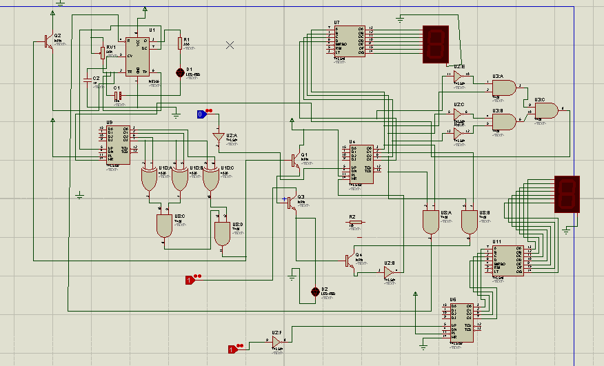
my problem is the 74ls 192 does not count up i try it in proteus and it works but when i implemented it in breadboard it doesn't work

---------- Post added at 11:25 ---------- Previous post was at 11:24 ----------

and the display is not stable also
 

this is my design


---------- Post added at 04:22 ---------- Previous post was at 04:19 ----------

this is my design
 

can't see the image clearly. it might be a connection problem. double check your circuit wiring, power and ground connections.
 

@blush

First of all, what is the purpose of this circuit? :-D Some parts are just standalone, those are not connected to the circuit.

- There is not a good idea to mix bipolar transistors and logical gates in the way you have.
- Need to connect some limiting resistors (100ohms) in between BCD decoder and 7 LEDs segment display
- Connect some pull-up resistors (10k ) from the not used ‘Count Up’ and ‘Count Down’ inputs to 5V power supply
 

Attachments

  • 74LS192 v2.png
    74LS192 v2.png
    41.2 KB · Views: 159
  • Like
Reactions: blush

    blush

    Points: 2
    Helpful Answer Positive Rating
the logic switch there represents a sensor.. what should i do with the transistor connection?

---------- Post added at 17:05 ---------- Previous post was at 17:02 ----------

i am making a conveyor using logic gates only.. the led represents the motor and it is a conveyor that is controlled by a sensor
 

In order to help you we need to have more details about functionality of the above circuit.
Can you provide state table/state diagram for it?
 

thnx to u mister_rf ur comment helps me a lot i solve this problem
 

Status
Not open for further replies.

Part and Inventory Search

Welcome to EDABoard.com

Sponsor

Back
Top