Continue to Site

Welcome to EDAboard.com

Welcome to our site! EDAboard.com is an international Electronics Discussion Forum focused on EDA software, circuits, schematics, books, theory, papers, asic, pld, 8051, DSP, Network, RF, Analog Design, PCB, Service Manuals... and a whole lot more! To participate you need to register. Registration is free. Click here to register now.

pov to display characters

Status
Not open for further replies.

Disha Karnataki

Full Member level 5
Joined
Jul 20, 2013
Messages
249
Helped
9
Reputation
18
Reaction score
8
Trophy points
18
Location
india
Activity points
2,231
i am doing a pov display using table fan so i have chosen ldr as sensor to detect the reference position.Everything is setup well & all mechanical arrangement is ready there are 3 speeds for this fan on motor it is written that ""rotating speed=1250rpm"" so the third speed or max speed is 1250rpm can anyone tell me how to find the rpm of lower & the middle speed without using tachometer?.
my another question is that i have tried to make the ldr sensor quite sensitive as i am using 8051 uc whose time duration to cause interrupt should not be less than 1.086us so now if i make calculations then the leds(led size=5mmin dia) with the sensor will be exposed to light for duration of 24.867us
so interrupt should occur & it should start displaying why isn't it doing i dont know!! is it that the sensor is not too much sensitive & should i prefer some other??
 

Hi Disha,

Its slightly ambigous as to whether you are using an LED or an LDR for detection. I hope you mean an IR LED, the LDR might be too slow for this.

First off, check whether your opto arrangement is actually working by moving the fan blades manually, and look for pulses on the CPU input pin; if not, post your detector schematic.

The max rotational speed of the fan is bound to reduce when you mount your PCB on the blade. So, there is no escaping a tacho or a frequency counter.

This is not as difficult as it sounds. There are numerous frequency counter designs on the internet; build one. Or let your optical detecor itself do the work, once its running.

Regards.
 

i am using ldr with led light to fall on it & it detects the light only for the initial speed & later it will not detect it so i am using now ir sensor with ir photo transistor 2n5777 i hope this will work..
 

Hi disha.. please dont use LDR sensor.. simply waste of time.. i have tried with LDR but it is not possible to detect start position as my speed was 1440rpm, better to use hall effect sensor, it worked fine for me

- - - Updated - - -

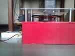
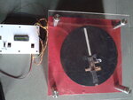
loo 2013-06-12 08.23.55.jpg2013-06-12 08.24.54.jpgk at my POV display

- - - Updated - - -

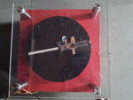
2013-06-12 08.25.10.jpg

i used LCD display to display speed of a motor..this POV is fully PC controlled.. whatever image we r creating in PC, that same image was displaying by LED's
 

what you say about using ir sensor??

- - - Updated - - -

i have now wired the sensor like this:https://www.google.co.in/search?q=i...%2Fhtml%2Ffree_space_optical_com.html;368;356
when i check using DMM across r2 it shows no deflection for the presence or absence of ir light i.e i had given a supply of 5v then it showed 4.78v across resistor & then no deflection in the value.
here i have used phototransistor 2n5777.
isn't this ckt correct??
i have even tried this way:https://www.google.co.in/search?q=i...ake-simple-infrared-sensor-modules%2F;580;540
with dmm to find collector voltage but no fluctuations in the volatge
 
Last edited:

hello,

i had given a supply of 5v then it showed 4.78v across resistor & then no deflection in the value.
wich one resitor ?
What values used for R1 and R2 ?

be carreful , with ambiant light wich could saturate the transistor.
In the dark R2 level voltage must be near 0V
 

it is given in one dig r1=270ohm & r2=10kohm.
& in this the values are:https://www.google.co.in/search?q=i...2Ftheremin_with_ir_distance_sensor%2F;800;305

tell me one thing will this circuit detect the ir rays in dark at high speed say 2000rpm is it that sensitive?? if anyone can give me proper description then may be i shall proceed with the circuit.
if i am not using 2n5777 then can i use the phototransistor as shown here:https://www.google.co.in/search?q=i...2Ftheremin_with_ir_distance_sensor%2F;800;305
 

From all above discussion u may work on sensing circuitry. Ok
But LCD is suitable for rapid changing data due to its response. So u consider this part also
 

hello,

Yes,
SFH484 emitteur at 880nM
and phototransistor SFH300 FA with centered response at 880nM
are correct type to use.
even a 2000 rpm => 33 Hz only
depends of the size of operture : when phototransitor can see the led
suppose : max width=5mm
and positionning of theses on diameter max=10cm..
so linked to linear speed..
Max width impulse could be 500µS ...large enough to be detected for a MCU.

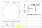
Image1.jpg
 

fine, what i did was initially i used ir led & photodiode as shown in your diagram & then tried sensing it then i realized that it was sensing the tube-light in my room rather than ir light(i mean more effectively at higher speeds it was sensing the tube light) i tried modifying the circuit but could not reduce ir photo-diode's affinity for ambient light so now i have thought of using simple led rather than ir led & making the room darker & now it's working well .

another doubt i have is about the programing:as @shaha2014 #4 post has said that the pov used to display whatever written on the computer i.e it is using serial communication(that is what i have understood) but, how does one do that because every character has different set of code & even every image has different set of code to be written then code will differ from character to character,letter to letter ,word to word & image to image & set of code will be different for images we want to get on pov then how is this done?? or may be i have mistaken somewhere
 

hello,

dot Matrix pixel definition (ex: 5x7 pixels) for each caractere (A..Z, 0..9 ..a..z)etc) so 96 chars
because no need to store non printable car 0 to 31 .
These matrix are stored inside table in RAM as constant value.
One char use 5 bytes to contain his matrix
so a Big ram area : 96 x 5 = 480 bytes ! must be used.
and you need also to define a buffer to receive the message you want to display.
ex: buffer[20]; in RAM if message is 20 chars long.
Your program explore this table to display the proper matrix caractere corresponding to each car in the buffer
to display them.
You need , for example, an UART link to send new message into the buffer for displaying a new message..
if you want to treat image.. so matrix must be 8x8 pixels ...and needs more RAM AREA

an example ; not for circular POV , but principle is very similar
with moving message pixel by pixel..
**broken link removed**
 

check my thread in problems facing in timer interrupts in microcontollers.
 

Status
Not open for further replies.

Similar threads

Part and Inventory Search

Welcome to EDABoard.com

Sponsor

Back
Top