Continue to Site

Welcome to EDAboard.com

Welcome to our site! EDAboard.com is an international Electronics Discussion Forum focused on EDA software, circuits, schematics, books, theory, papers, asic, pld, 8051, DSP, Network, RF, Analog Design, PCB, Service Manuals... and a whole lot more! To participate you need to register. Registration is free. Click here to register now.

Pin voltage issue

Rajinder1268

Full Member level 3
Joined
Mar 20, 2021
Messages
162
Helped
1
Reputation
2
Reaction score
4
Trophy points
18
Activity points
1,228
Hi all,
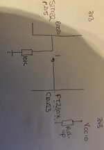
We are trying to use a FT230x CBUS3 to control the BOOT status of a STM32F215.
The boot pin of the STM32 is tied to 0V via a 10K pull down.

The internal pull up of the FT device is used to toggle the boot pin. I have attached a diagram.

We are seeing a voltage of 0.5V which does not meet the requirements for the VIH of the STM32 to register as a logic 1. It has the following criteria 1.75V<VDD<3.6V

However, when the pull down is changed to 100K we get around 2.2V.

I have measured the value of the internal pull up of the FT230 by measuring the current going into the CBUS3 pin and VCcIO is 3.3V. Which is around 66K.

This all makes sense. My question is why when the pull down is at 10K can I still enter boot mode when the voltage going into the STM32 is 0.5V? Sometimes it fails.

Thanks in advance.
 

Attachments

  • IMG_20231020_071530.jpg
    IMG_20231020_071530.jpg
    3.2 MB · Views: 52
Hi,

I really don't get it.
Why a lengthy discussion about pull ups and crappy voltage levels, while the FTDI is able to drive clean levels?
As can be seen in the table of post#17 the FTDI provides a bunch of output drive options.
Just use them. No need to solder.

The table shows the ability to set drivestrength to 4mA, 8mA, 12mA, 16mA ... --> even the lowest mode will drive clean levels.
But if you set it to "not drive" the output it will use this crappy pull up. But why should one?
If "weak driving" is the root cause, thanks FTDI, the chip is able to adjust.

Please anyone tell me what's happening here.

Klaus
 
Programmable drive strength is provided for DBUS pins. I didn't yet clearly see, if CBUS3 has active pull-up capability when configured as GPIO, possibly not.
--- Updated ---

Have to correct myself CBUS does also have programmable current strength, but not sure if it provides active pull-up.
 
Last edited:
>This all makes sense. My question is why when the pull down is at 10K can I still enter boot mode when the voltage going into the STM32 is 0.5V? Sometimes it fails.

0.5V is too close to the threshold for BOOT0 because it is a special port with lower thresholds.
Instead ensure it always below 0.4V for reliable logic "0". ( or even < 0.3V for more margins) The specs are in #9

I assume the FTDI is not initialized yet and thus its port is floating as an input with passive 66k nominal input and this is why it needs to execute BOOT0.

Correct me if my assumptions are wrong.
The 10K should have the BOOT0 pin at 0V, then the FTDi device toggles this line high. This should then get into system memory bootloader. However the voltage is at 0.5V. The Minimum level that the BOOT0 of the STM32 (ViH) should be 0.17VDD + 0.7V which is 1.26V.
>This all makes sense. My question is why when the pull down is at 10K can I still enter boot mode when the voltage going into the STM32 is 0.5V? Sometimes it fails.

0.5V is too close to the threshold for BOOT0 because it is a special port with lower thresholds.
Instead ensure it always below 0.4V for reliable logic "0". ( or even < 0.3V for more margins) The specs are in #9

I assume the FTDI is not initialized yet and thus its port is floating as an input with passive 66k nominal input and this is why it needs to execute BOOT0.

Correct me if my assumptions are wrong.
The Boot0 is at 0.5V, when toggled from 0 to 1 from the FTDi device. ViH (min) of the STM32 is 0.17VDD +0.7. This equals 1.26V. So how is this 0.5V recognised as a logic 1. I am not entirely sure if I need to add 0.7V in the equation for ViH. If not then this becomes closer to the 0.5V.

The internal pull up of the FTDi is 66K. When I changed the pull down to a 100K, we had 1.9V at Boot0 which according to the theory allows bootloader to be accessed.

It's the first condition that I can't understand with the 10K pull down.
 
As demonstrated in #9

BOOT0 has lower thresholds than I/O ports.
Vil= 0.43 V max = 0.1 * Vdd+0.1 V <<<<< this means use 10% of the 66k pull-up for pull down = 6k6 max
Vih = 1.26 V min = 0.17 * Vdd+0.7 V
>> how is this 0.5V recognised as a logic 1.

The above spec means any voltage between 0,43 and 1.26 is an invalid logic level which includes 0.5V
Invalid or indeterminate means it may be either a 0 or a 1.
 
>> how is this 0.5V recognised as a logic 1.

The above spec means any voltage between 0,43 and 1.26 is an invalid logic level which includes 0.5V
Invalid or indeterminate means it may be either a 0 or a 1.
Ok, I understand. I was mis interpreting the ViH value. So the remedy is to have the pull down decreased to allow the Boot0 voltage to be less than 0.43V. Also when toggled it needs to be greater than 1.26V. The recommendation was to have it at 6.6K?
 
Thanks for finally clarifying about intended and observed circuit behaviour.

If it's so, I would choose e.g. 2k pull-down. We could have been there two days before...
 
That is the max value = 6.6k yes. for passive logic 0.
The min value is 1.26V/2mA = 0.63 k for active logic 1.
I can see that a stronger pull up will keep the Boot0 pin below 0.43V. But when the FTDi is toggling, i.e. Internal pull up 66K. This does not then go above 1.26V. Forming a potential divider with the 6.6K. Am I missing something?
 
That
Am I missing something?
That's the question. I don't yet understand if CBUS3 pin in GPIO output mode provides active pull-up or not. It's not clearly specified in the datatsheet. If there's no active pull-up feature, you definitely have a problem with initial state before FT230x configuration is loaded from EEPROM. Default (unconfigured) state of CBUS3 is weak pull-down in USB suspend and weak pull-up when connected.

Can you briefly explain which CBUS bit-bang commands your are using to control the pin?
 
That

That's the question. I don't yet understand if CBUS3 pin in GPIO output mode provides active pull-up or not. It's not clearly specified in the datatsheet. If there's no active pull-up feature, you definitely have a problem with initial state before FT230x configuration is loaded from EEPROM. Default (unconfigured) state of CBUS3 is weak pull-down in USB suspend and weak pull-up when connected.

Can you briefly explain which CBUS bit-bang commands your are using to control the pin?
I believe it's done by using FTPROG utility. Unfortunately I do not have access to code.
 
I can see that a stronger pull up will keep the Boot0 pin below 0.43V. (WHAT VALUE) But when the FTDi is toggling, i.e. Internal pull up 66K. This does not then go above 1.26V. (SO WHAT IS THE VALUE) Forming a potential divider with the 6.6K. Am I missing something?
When stating a problem do not use adjectives like stronger and higher and inaccurately defining a pull-down as pullup.
Rather report actual values Ohms ,Volts and programmed current level of the FTDi.

This should be a simple voltage divider problem, but relies on accurate test results and driver states 0 or 1 (or off) and define all the assumptions.

The driver acts like an ideal voltage but with a series Ron that has an FTDi programmed current level for a fix voltage drop in the code. However, the minimum is 2 mA and should be sufficient unless there is something missing in your description.

Try again.
No problems, I will have another look.
 

LaTeX Commands Quick-Menu:

Similar threads

Part and Inventory Search

Welcome to EDABoard.com

Sponsor

Back
Top