Continue to Site

Welcome to EDAboard.com

Welcome to our site! EDAboard.com is an international Electronics Discussion Forum focused on EDA software, circuits, schematics, books, theory, papers, asic, pld, 8051, DSP, Network, RF, Analog Design, PCB, Service Manuals... and a whole lot more! To participate you need to register. Registration is free. Click here to register now.

PicKit 2 FULL with TH components - Need help with layout

Status
Not open for further replies.
pickt2 download

Perhaps you can check them of on DMM for identifying the leads and accordingly swap the pins of transistors. Specific care is needed for proper placement of any device.

i too assembled Nishal' PCB only

but i use 2N3904(6) and position them accordingly

if BS170 is Motorola item, it follows DGS order

24C512 is little more hungry and thus loads the USB power supply.How ever, we can mount them later also.

connect a 1K resistor and diode in series to power supply in the forward dirction, the diode should develop a drop of approximately 0.25V

DMM forward check in diode range would show less that 1/3rd of what 1N4148 shows. Thus to check for a schottky diode is not difficult.

you need to use a box type capacitor or at the worst a disc cap and not electrolytic.
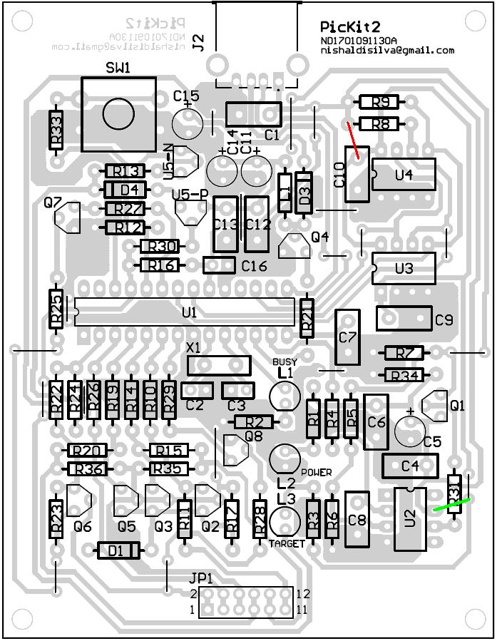
In the attached ppcb has the U5P FET underneath, thus invisible from top.
 

buy pickit 2 india

@Nishal , can someone post the code of U2,U3 and U4, or U2 ,U3 and U4 can be
missing ?????
 

irlml6402+replacements

lgeorge123 said:
@Nishal , can someone post the code of U2,U3 and U4, or U2 ,U3 and U4 can be
missing ?????

U2 is an Rail to Rail (input&output) op-amp. As such no code expected.
we need not even mount the EEproms(U3 and4) they would be needed in case we use other facilities like programmer-to-go, or as a Logic tool, i feel.

Sarma
 

replacement transistor bs250

mvs sarma said:
lgeorge123 said:
@Nishal , can someone post the code of U2,U3 and U4, or U2 ,U3 and U4 can be
missing ?????

U2 is an Rail to Rail (input&output) op-amp. As such no code expected.
we need not even mount the EEproms(U3 and4) they would be needed in case we use other facilities like programmer-to-go, or as a Logic tool, i feel.

Sarma

Ya, the eeproms is for the programmer-to-go as we can also place a 24LC1024 as well if u need more capacity.

Just found out today PICkit2 can program PIC without a PC. Thats what sarma said:programmer-to-go feature. We load the required hex file & power it up with a mini USB 5V power adapter & press the red button to program PIC as many times as we needed. So I think this thru hole version will do the job too.

I'll try to change some components & try again.
 

2n7000 substitute

me_guitarist said:
mvs sarma said:
lgeorge123 said:
@Nishal , can someone post the code of U2,U3 and U4, or U2 ,U3 and U4 can be
missing ?????

U2 is an Rail to Rail (input&output) op-amp. As such no code expected.
we need not even mount the EEproms(U3 and4) they would be needed in case we use other facilities like programmer-to-go, or as a Logic tool, i feel.

Sarma

Ya, the eeproms is for the programmer-to-go as we can also place a 24LC1024 as well if u need more capacity.

Just found out today PICkit2 can program PIC without a PC. Thats what sarma said:programmer-to-go feature. We load the required hex file & power it up with a mini USB 5V power adapter & press the red button to program PIC as many times as we needed. So I think this thru hole version will do the job too.

I'll try to change some components & try again.

perhaps it involves additional hardware sold by Microchip, if i remember. basically get it to work . I dont get your location (Malaysia, if I remember.) you try to get ZHCS1000diode and solder it by hook or crook (SMD ) to this board at D4 location

You might overcome the other issues. Perhaps you need to replace all electrolytic caps by Tantalum caps. As i said, please ensure your positioning of all semiconductors and any such polarised components like electrolytic caps etc

Sarma
 

mosfet bs250 mexico

perhaps it involves additional hardware sold by Microchip, if i remember. basically get it to work . I dont get your location (Malaysia, if I remember.) 'I'm from Malaysia'you try to get ZHCS1000diode and solder it by hook or crook (SMD ) to this board at D4 location

You might overcome the other issues. Perhaps you need to replace all electrolytic caps by Tantalum caps. As i said, please ensure your positioning of all semiconductors and any such polarised components like electrolytic caps etc

Sarma

I think my BC639/640 is NXP.

Meaning I need to replace D4 with ZHCS1000?can a 1N4007 replace 1N5818/9?

I used polyester cap for all .1uf will this be any problems? This cap was removed from an old damaged video player of Hitachi & I quite sure the cap are still well.

0.47uf, 47 uf & 10uf is E-cap, I'll change 0.47uf to polyester or ceramic type.

Lets make this project successful.
 

pic kit 2 full

me_guitarist said:
perhaps it involves additional hardware sold by Microchip, if i remember. basically get it to work . I dont get your location (Malaysia, if I remember.) 'I'm from Malaysia'you try to get ZHCS1000diode and solder it by hook or crook (SMD ) to this board at D4 location

You might overcome the other issues. Perhaps you need to replace all electrolytic caps by Tantalum caps. As i said, please ensure your positioning of all semiconductors and any such polarised components like electrolytic caps etc

Sarma

I think my BC639/640 is NXP.

Meaning I need to replace D4 with ZHCS1000?can a 1N4007 replace 1N5818/9?

I used polyester cap for all .1uf will this be any problems? This cap was removed from an old damaged video player of Hitachi & I quite sure the cap are still well.

0.47uf, 47 uf & 10uf is E-cap, I'll change 0.47uf to polyester or ceramic type.

Lets make this project successful.
the query is irrelevant. as the diode concerned is schottky type with Vforward drop less than .25 V
how ever, first replace electrolytic caps and try
NXT make 639/640 follow the ECB order. as per the datasheet, so no issues except for Hfe.
.
 

I have partial success. I removed the U2, shorted the D&S leads of Q1 and then ran the device for tests other than calibration. it passes. perhaps this can be tried and let us bring it to operation first
try to programm few chips and offer comments me_guitarist !!
 

mvs sarma said:
I have partial success. I removed the U2, shorted the D&S leads of Q1 and then ran the device for tests other than calibration. it passes. perhaps this can be tried and let us bring it to operation first
try to programm few chips and offer comments me_guitarist !!
.

OK

Added after 1 hours 48 minutes:

Hi Sarma,

Just tried yr method, it only can read device can't program it.
 

me_guitarist said:
mvs sarma said:
I have partial success. I removed the U2, shorted the D&S leads of Q1 and then ran the device for tests other than calibration. it passes. perhaps this can be tried and let us bring it to operation first
try to programm few chips and offer comments me_guitarist !!
.

OK

Added after 1 hours 48 minutes:

Hi Sarma,

Just tried yr method, it only can read device can't program it.
I was able to program too . i tried with 16F628A. I call it JUNEBUG less tutor.

Sarma
 

hi sarma,

I replace the 1N5818/9 & rotate Q1 now its ok to program(still can't calibrate). I think the shopper has give me the wrong diode.

TARGET LED doesn't lit.Hows yr LED?
 

ALL oK
calibration part , we disabled as we have removed the U2 and shorted Q1. please remove the Q1. if you rotate, the diode conducts and give you a drop of .5V acros the device.
this part of the schematic has to be studied for its behavior, however you need to use an opamp that has input and output rai to rail workability.

Regarding the yellow lamp. please check the anode and cathode. the cathode (marked side is to face the Pin25 and the anode towards the 470 ohm resistor and then Vusb. it si ample to check by removing the main chip and by giving a Gnd at pin 25.
a schematic of part of schematic is attached.
 

mvs sarma said:
ALL oK
calibration part , we disabled as we have removed the U2 and shorted Q1. please remove the Q1. if you rotate, the diode conducts and give you a drop of .5V acros the device.
this part of the schematic has to be studied for its behavior, however you need to use an opamp that has input and output rai to rail workability. (I use MCP6271)

Regarding the yellow lamp. please check the anode and cathode. the cathode (marked side is to face the Pin25 and the anode towards the 470 ohm resistor and then Vusb. it si ample to check by removing the main chip and by giving a Gnd at pin 25.
a schematic of part of schematic is attached.

The yellow LED are positioned correctly still not lit up.

Added after 50 minutes:

The Programmer-To-Go features is not working.

Added after 17 minutes:

Hi Sarma,

Do I need to revise the board as wizpic mentioned earlier? His circuit does connect to Vusb+5V. I double checked the current circuit doesn't have Vusb+5V.
 

1. perhaps your lamp is bad or the sries resistor is bad
as i suggested, you don't go by the marking on the component but electrically check whether it glows by a local test of giving earth at the respective PIC pin. if not reverse the led mounting and then repeat test. on side 5V and other side earth is a simple issue.


2. please let us first bring the pickit to full working condition. only then, the programmer. It needs additional hardware please read the user guide

3. the terminology has been different for Microchip's and cm29's schematics. i am to see what wizpic told?

i wonder whether wizpic is referring to an earlier diagram of cm29. btw there is a simple wire link needed to power the 2 eeproms and the yellow lamp as well. i mentioned it earlier to you.
see attached photo

Sarma
 

mvs sarma said:
1. perhaps your lamp is bad or the sries resistor is bad
as i suggested, you don't go by the marking on the component but electrically check whether it glows by a local test of giving earth at the respective PIC pin. if not reverse the led mounting and then repeat test. on side 5V and other side earth is a simple issue.
I simply connect a wire after the 470R(Yellow LED) to Vusb+5V, now everything works perfectly, programmer-to-go working, Yellow LED lit up. I didn't remove U2 as well. I still can't calibrate it but do this does matter?:D


2. please let us first bring the pickit to full working condition. only then, the programmer. It needs additional hardware please read the user guide

3. the terminology has been different for Microchip's and cm29's schematics. i am to see what wizpic told?

i wonder whether wizpic is referring to an earlier diagram of cm29. btw there is a simple wire link needed to power the 2 eeproms and the yellow lamp as well. i mentioned it earlier to you.
see attached photo.
No attachment.
He is referring to Nishal's layout.


Sarma

Finally, the thru hole version is fully worked now.

Added after 4 minutes:

The green color is what I done.
 

me_guitarist said:
mvs sarma said:
1. perhaps your lamp is bad or the sries resistor is bad
as i suggested, you don't go by the marking on the component but electrically check whether it glows by a local test of giving earth at the respective PIC pin. if not reverse the led mounting and then repeat test. on side 5V and other side earth is a simple issue.
I simply connect a wire after the 470R(Yellow LED) to Vusb+5V, now everything works perfectly, programmer-to-go working, Yellow LED lit up. I didn't remove U2 as well. I still can't calibrate it but do this does matter?:D


2. please let us first bring the pickit to full working condition. only then, the programmer. It needs additional hardware please read the user guide

3. the terminology has been different for Microchip's and cm29's schematics. i am to see what wizpic told?

i wonder whether wizpic is referring to an earlier diagram of cm29. btw there is a simple wire link needed to power the 2 eeproms and the yellow lamp as well. i mentioned it earlier to you.
see attached photo.
No attachment.
He is referring to Nishal's layout.


Sarma

Finally, the thru hole version is fully worked now.

CONGRATULATIONS.
However, as time passes, you need 3.3v devices programming and even if not, (imagining that you might be a student) we need to maintain academic interest, as to why we are missing and this will help buildup your analytical capabilities.
I hope this site and all of us about building a better engineer for tomorrow.

Ofcourse i am retired person and still I am interested as to where we are missing the reason.
Sarma

Dear Sarma,

Thanks for yr words.
 

@Computerman29 can u post the working of your pickit2.

Whether calibration is successful and working status on 'troubleshooting' menu. This will help us to analyze further.

Nishal
 

nishal said:
@Computerman29 can u post the working of your pickit2.

Whether calibration is successful and working status on 'troubleshooting' menu. This will help us to analyze further.

Nishal

Hi Nishal,

I used yr layout & its fully function. Pls check previous post. However, it can't be calibrate.

Trouble shooting all passed.

Thanks for the nice layout.

Regards
 

Status
Not open for further replies.

Similar threads

Part and Inventory Search

Welcome to EDABoard.com

Sponsor

Back
Top