Kova
Member level 1
Hi all,
I have an old arcade games with a CGA (Hsync 15kHz Vsync 60Hz) and EGA (Hsync 25kHz Vsync 60Hz) monitors and I want to interface with a PIC.
The arcade monitors, than a VGA monitors (Hsync 31kHz Vsync 60Hz), work with a different Hsync freq.
The video signals present on the monitor are: R,G,B, Sync, Ground (here you will find the complete pinout of jamma standard: **broken link removed**)
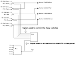
So, this is (a part of) what I would like to do:
I downloaded from here: http://www.pic24.ru/doku.php/en/osa/articles/vga_game the source code, but it ìs written to work with a VGA monitor.
In the vga_game_main.c file there is this code:
This is used to generate the 31,469kHz sync.
Which timer register I have to modify to generate a 15.75kHz sync freq?
In the arcade monitor interface there aren't Hsync and Vsync signals but only the Sync signal, so both H/Vsync signals (output from the pic) will be connected together in the same point (P point on the jamma connector).
This connection (H and Vsync connected together) is also used when it connects a PC to an arcade monitor (in this case the Hsync video frequency is forced to work at 15kHz by a dedicated software).
Thanks a lot for any advice.
Bye
I have an old arcade games with a CGA (Hsync 15kHz Vsync 60Hz) and EGA (Hsync 25kHz Vsync 60Hz) monitors and I want to interface with a PIC.
The arcade monitors, than a VGA monitors (Hsync 31kHz Vsync 60Hz), work with a different Hsync freq.
The video signals present on the monitor are: R,G,B, Sync, Ground (here you will find the complete pinout of jamma standard: **broken link removed**)
So, this is (a part of) what I would like to do:
I downloaded from here: http://www.pic24.ru/doku.php/en/osa/articles/vga_game the source code, but it ìs written to work with a VGA monitor.
In the vga_game_main.c file there is this code:
Code:
    //------------------------------------------------------------------------------
    // Timers
    //------------------------------------------------------------------------------

    T2CON = 0x1C;   // post = 4;
    T1CON = 1;
    PR2 = (char)(1.2 * 318/4 - 1);      // 31.8 us

    CCP1CON = 0x0C;         // PWM mode
This is used to generate the 31,469kHz sync.
Which timer register I have to modify to generate a 15.75kHz sync freq?
In the arcade monitor interface there aren't Hsync and Vsync signals but only the Sync signal, so both H/Vsync signals (output from the pic) will be connected together in the same point (P point on the jamma connector).
This connection (H and Vsync connected together) is also used when it connects a PC to an arcade monitor (in this case the Hsync video frequency is forced to work at 15kHz by a dedicated software).
Thanks a lot for any advice.
Bye
Last edited:
