Continue to Site

Welcome to EDAboard.com

Welcome to our site! EDAboard.com is an international Electronics Discussion Forum focused on EDA software, circuits, schematics, books, theory, papers, asic, pld, 8051, DSP, Network, RF, Analog Design, PCB, Service Manuals... and a whole lot more! To participate you need to register. Registration is free. Click here to register now.

Photodiode Amplifier - BW Problem

Status
Not open for further replies.
What do you mean with " if the source (photodiode) capacitance already allows a gain > 10."
I referred to the Wideband Photodiode Transimpedance Amplifier circuit at page 1 of the OPA657 datasheet.
I have build another device with universal capacitor (Rf=2k2, Cf=1pF) and the same result was seen
Cf=1pF won't achieve stable operation with OPA657, which OP did you use there?

I understand, that you are referring to an apparent high frequency gain drop at high input levels, while the frequency response is correct with optical attenuation? Are you sure, that the bias circuit is keeping the voltage level at high input level?
 

Hi FvM,

Thanks for your help. Please see below.

I referred to the Wideband Photodiode Transimpedance Amplifier circuit at page 1 of the OPA657 datasheet.

Cf=1pF won't achieve stable operation with OPA657, which OP did you use there?

Ah, ok. I used the same PCB design, same Opamp. But I used a 2.2k feedback resistor and only one feedback capacitor (1pF) instead of the C tee network.

I understand, that you are referring to an apparent high frequency gain drop at high input levels, while the frequency response is correct with optical attenuation? Are you sure, that the bias circuit is keeping the voltage level at high input level?

Yes, when high input level light is used the gain drops starting at 100kHz, but if opticall attenuation is used, it seems it works correctly. That's what I have measured.
The bias circuit voltages seems correct. Please take a look to a reply I did before, where I wrote DC levels on the Opamp pins. It is consistent with the simulation.

Best regards!
Horacio
 

It would be worthwhile looking at the output signal with an oscilloscope in both cases (with & without optical attenuation). Are you sure the modulation is 1/500 of the optical power? That seems very low. When I have worked with modulating lasers the modulation has usually been around 80%.

Keith.
 
It would be worthwhile looking at the output signal with an oscilloscope in both cases (with & without optical attenuation). Are you sure the modulation is 1/500 of the optical power? That seems very low. When I have worked with modulating lasers the modulation has usually been around 80%.

Keith.

Hi Keith,

I've measured the output in both conditions with the oscilloscope (60MHz BW). The transmitance curve is on the original post.
I have control over the modulation. I'm using a diode laser that allow to control the modulation. It has a 50ohm input, so I connect the generator directly to it and then set the amplitude of the signal. I need to work in those conditions in order to simulate the conditions present on the experiment where the device will be used.

Thanks!
Regards!
Horacio
 
Last edited:

So does the bandwidth improve as you reduce the modulation? My suggestion of looking at the output with an oscilloscope is to see what the peak to peak signal is, on top of the DC output level.

Keith.
 
So does the bandwidth improve as you reduce the modulation? My suggestion of looking at the output with an oscilloscope is to see what the peak to peak signal is, on top of the DC output level.

Keith.

Actually the bandwidth seems to be improved when optical attenuation is used (all the components of the signal are attenuated). I tested with several modulation index (without optical attenuation) and the bandwidth was not improved.
I will follow your suggestion.

Thanks!
Horacio
 

I think the possibility of oscillation is still there. I would suggest trying a different (slower) opamp with a simple capacitor across the feedback. Something with 100MHz bandwidth should be more than adequate and reduce the likelihood of oscillation.

Keith.
 
I think the possibility of oscillation is still there. I would suggest trying a different (slower) opamp with a simple capacitor across the feedback. Something with 100MHz bandwidth should be more than adequate and reduce the likelihood of oscillation.

Keith.

Yes, I think you're right. Yesterday I've connected the second device (Rf=2.2k Cf=1pF no Tee) without laser signal and I saw a ~294MHz signal in the oscilloscope(BW=60MHz). I will check again with the spectrum analyzer to check the amplitude of it. So it's oscillating.

Could you please recomend me an opamp with the features you mentioned?

Thanks!
Horacio
 

I don't know where you are and so which devices are easy to get hold of for you, and I am not sure which package you have but the following may be suitable:

AD8027, AD829, THS4031, MAX4430.

I haven't used any of those. The problems is my designs tend to be either high speed for laser rangefinders (500MHz to 1GHz) or very high gain for instrumentation (>10M ohm transimpedance). You application is in the middle of that range. The only ones I have used for transimpedance amplifiers that are close to your requirements are the MAX412, LT1028 and AD8655 which might just be OK - they may be a little slow. They might be worth a quick simulate.

Keith.
 
I saw a ~294MHz signal in the oscilloscope
Yes, it has to be expected with OPA657, because it's no unity gain stable. I don't know however, if the oscillations are also causing the observed frequency response, but at least, it's not normal operation.
 
Hi again,

Today I have finally measured with spectrum analyzer and also the signal at the output of the device. Please let me clarify the devices I've been using and the corresponding measurements.

I build 2 devices that are the following:
Device Nr.1 --- Device Nr.2
Device_Nr1.JPG --- Device_Nr2.JPG

Please note the only differences are:
- The photodiode (Which have a very similar CD)
- Decoupling capacitors
- Feedback capacitor

I've obtained the following results:

Spectrum Analyzer Measurement
Reference: -10dBm

Device Nr.1
On the display of the Instrument was only seen a signal 545 MHz / -19.5dBm

Device Nr.2
On the display of the Instrument was seen the following signals:
f0 = 287.5MHz / -3.3dBm
f1 = 575 MHz / -37 dBm
f3 = 865 MHz / -26 dBm

These measurements were done without any laser signal. Just the biased device and nothing else.

Output signal Measurement

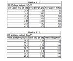
Following the suggestions from Keith, I have measured the following values, in accordance with the previous images.
Device Nr.1 & Device Nr. 2
Measurements.jpg
Note: Please note I'm using the "," as decimal symbol.

I think certainly, you were right when told me the device is oscillating. So what's next? What can I do now? Could you please help me with this?

******​

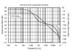
On the other hand, I was reading the OPA657 datasheet, and stoped mainly on the following graph of AOL.
OPA657_AOL.jpg

There you can see, the Opamp have the first pole around 100kHz, and of course also de phase lag. I think to my self if this has something to do with the frequency response that I've measured on my device. Because I still don't understand why oscillation at higher frequency could roll off the gain at 100kHz. Could you please explain me a bit of it or the main idea? or just tell me where to read?

Thanks a lot to all,
Horacio.


P.S.: I've attached the TINA circuits just in case you want to test them. Please note I set up the DC and AC current of the generators in accordance with the measurement above.
View attachment Device_Nr1&2.rar
 

When you add small decouplers on high speed opamps you still need to keep the large ones as well.

I notice you have a 1N4148 across the photodiode. I assume this is just for modeling, not in the actual circuit, but it will screw up your simulations.

My simulations show ringing around 125MHz with your first circuit, around 250MHz with your second which seems to be around half the frequency you are seeing.

I don't understand the "Vin Laser". I assume this is the modulating voltage you are applying to the laser.

The low apparent output voltage on the second circuit suggests strong oscillation which is what your results show.

You cannot make sense of the measured results while the opamps are oscillating. You need to stop the oscillations first.

You really need to stop using those opamps and use something with a more manageable bandwidth.

The fact that the first polse of the OPA637 is at 100kHz is not relevant.

Keith.
 
Just a thought - do you even need a transimpedance amplifier? With just 1k or so of transimpedance you could just use a 1k resistor to ground then buffer it. While I have used and designed transimpedance amplifiers with just a few k ohms impedance it is usually when I am trying to get 1GHz bandwidth. For 10MHz I am not sure it is necessary.

Keith.
 
Hi Keith,
Please see below. Thanks!

When you add small decouplers on high speed opamps you still need to keep the large ones as well.

Ok, so I will solder 100nF and 100pF to decouple the source. Is that ok?

I notice you have a 1N4148 across the photodiode. I assume this is just for modeling, not in the actual circuit, but it will screw up your simulations.

Yes you're right. Actually I put it just to show the way I'm using/biasing the photodiode. I think there is no difference to bias with negative or positive voltage and use the corresponding cathode/anode to the opamp input. But not sure anymore.

My simulations show ringing around 125MHz with your first circuit, around 250MHz with your second which seems to be around half the frequency you are seeing.

I don't understand the "Vin Laser". I assume this is the modulating voltage you are applying to the laser.

Yes, right. The Vin Laser is that.

The low apparent output voltage on the second circuit suggests strong oscillation which is what your results show.

Well, actually the Photodiode of device nr.2 have a smaller area and have no lens attached to it. Maybe that is another reason about the lower output voltage. But, yes, the oscillation seems to be stronger on it.

You cannot make sense of the measured results while the opamps are oscillating. You need to stop the oscillations first.

You really need to stop using those opamps and use something with a more manageable bandwidth.

Ok, I will try to find/buy any of the Opamps you recommend me. I will check if I can find them here (Buenos Aires, Argentina) or need to import them.

The fact that the first polse of the OPA637 is at 100kHz is not relevant.

Ok, thanks.

keith1200rs said:
Just a thought - do you even need a transimpedance amplifier? With just 1k or so of transimpedance you could just use a 1k resistor to ground then buffer it. While I have used and designed transimpedance amplifiers with just a few k ohms impedance it is usually when I am trying to get 1GHz bandwidth. For 10MHz I am not sure it is necessary.

Keith.

My first thought, after reading the reference book below, was to improve bandwith, and what you propose is what the book doesn't recommend to do.
On the other hand, I'm not sure I can recover the very low modulated signal without amplification.

Ref.book: Photodiode Amplifiers Op Amp Solutions - Jerald G. Graeme., Mc Graw Hill.

Thanks a lot for your answer
Best regards.
 

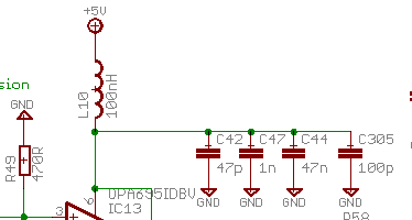
Personally, I use quite a few values. I cannot be certain that all of them are required in all cases, but I have often ended up with 4 values to remove oscillations and poor flatness on broadband amplifiers:

71_1287156286.gif


If you don't use a transimpedance amplifier you will still need a voltage amplifier (AC coupled) to boost your signal up to a reasonable size. I am not saying it is the "best" way, but with such a low bandwidth and gain it is worth considering.

Keith.
 
Personally, I use quite a few values. I cannot be certain that all of them are required in all cases, but I have often ended up with 4 values to remove oscillations and poor flatness on broadband amplifiers:

If you don't use a transimpedance amplifier you will still need a voltage amplifier (AC coupled) to boost your signal up to a reasonable size. I am not saying it is the "best" way, but with such a low bandwidth and gain it is worth considering.

Keith.

Thanks for the image of the decoupling capacitors. I will try with that configuration.
I understand your point about voltage amplifications. It's a valid option I
don't discard. Nowadays I was considering the posibility to have two stages,
first TIA with lower Gain (1 or 2) and then a second stage to amplify only the
AC signal.

Best regards,
Horacio
 
Last edited:

That's a valid option. The decouplers I posted were part of a system with 3 stages of AC amplification after the transimpedance amplifier (a MAX3864).

Keith.
 
Keith,

Just one doubt about the decoupling circuit you sent. What do you use as
the decoupling inductor 100nHy? Do you use a choke or chip ferrite?
Do you place it near the opamp pin ?

Thanks!
Horacio
 

I usually put it next to the opamp but it doesn't really matter too much - a bit of copper will just increase the inductance. Its main use is to prevent coupling of high frequencies from other stages, along with the decouplers. The important thing to get next to the opamp is the decoupling capacitors, with the lowest value closest to the opamp. I use wirewound chip inductors with a high SRF. Bear in mind this was for a circuit working at around 1GHz - it may be overkill for your circuit (although as yours is oscillating, maybe not;-)

Keith.
 
Hi again Keith,

I'm trying to follow your suggestions about to use another slower opamp.
I couldn't find any of those you recommend me here in Argentina, but I have a few units of the following:

1.- LT1806CS8
2.- TSH350IDT
3.- **broken link removed**
4.- **broken link removed**


Could you please advise me if I can "test" with any of these in order to achieve a better behavior?

The spice model is not available for alll of them so the simulation maybe not be a possiblity.

Thanks a lot for your help.
Best regards,
Horacio
 
Last edited:

Status
Not open for further replies.

Similar threads

Part and Inventory Search

Welcome to EDABoard.com

Sponsor

Back
Top