Continue to Site

Welcome to EDAboard.com

Welcome to our site! EDAboard.com is an international Electronics Discussion Forum focused on EDA software, circuits, schematics, books, theory, papers, asic, pld, 8051, DSP, Network, RF, Analog Design, PCB, Service Manuals... and a whole lot more! To participate you need to register. Registration is free. Click here to register now.

[SOLVED] photodiode amplification circuit

Status
Not open for further replies.

sjbaek

Newbie level 4
Joined
Nov 21, 2023
Messages
6
Helped
0
Reputation
0
Reaction score
0
Trophy points
1
Activity points
41
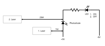
1. When only photos, light-emitting diodes, and resistors are used and only 9V power is applied, the distance is close to the strong infrared signal (remote control signal), but it does not work even if it falls off.

2. In order to solve the problem of No. 1, I want to output a constant current (voltage) even if I receive a little signal from the photodiode.
 

It would be better if you can elaborate your problem with detail including relevant schematic diagrams etc.
 

1. When you only use photos, light-emitting diodes, and resistors and only apply 9V power, a close signal works, but a short distance away does not work.

2. In order to solve the problem of No. 1, I want to output a constant current (voltage) even if I receive a signal from the photodiode.
캡처.PNG

캡처2.PNG
 

Attachments

  • 캡처.PNG
    캡처.PNG
    20.8 KB · Views: 65

Are you trying to duplicate a remote control signal or detect a continuous IR light?
AC detection is much more sensitive with IR receivers made by Vishay. These have BPF and AGC to handle a wide range of signal levels and block interference with a black daylight-blocking lens. The carrier frequency is fixed but you may select ones from 30 kHz to 56 kHz as I recall.

These can achieve 25 m or more.

 
Last edited:

    bassa

    Points: 2
    Helpful Answer Positive Rating
Some issues with post #3 information:

* Photodiode is the wrong way round
* if you have only 9V, then the reference (other pole) should be called 0V or GND. Using +9V and -9V makes a total of 18V.
* If your system works for 1M, then it may or may not work on 25m. It depends on how much of laser beam hits the active area of the photo diode.
In more detail: it depends on (1) laser output area, (2) laser divergency angle, (3) active photodiode area .. and more.
* in your sketch I was confused, because there are two lasers (but I guess there is only on) and further the arrows go from the Laser to the electrical wires of the photodiode.
To differentiate between laser beam and electrical wires I recommend to point the beams to the diode (by making them non_horizontal) ... and make them stop (with a little space) before the photodiode.

I guess what you are looking for is
* an amplifier (if you want to measure the intensitiy)
* or a comparator (if you just want ON/OFF)

And yes, like Tony said, IR receivers with built in optical filters, built in electrical filters and built in amplifiers ... could give a good and reliable solution. Cheap, too.

Indeed I expect a more clear description what all this is used for.

Klaus
 

    bassa

    Points: 2
    Helpful Answer Positive Rating
Are you trying to duplicate a remote control signal or detect a continuous IR light?
AC detection is much more sensitive with IR receivers made by Vishay. These have BPF and AGC to handle a wide range of signal levels and block interference with a black daylight-blocking lens. The carrier frequency is fixed but you may select ones from 30 kHz to 56 kHz as I recall.

These can achieve 25 m or more.


Are there any DIPs or anything larger in size?
I received the delivery, but it is too small to work. There is no separate precision equipment.
 

Are there any DIPs or anything larger in size?
I received the delivery, but it is too small to work. There is no separate precision equipment.
If you have read the link or other information about IR receivers, you know that they are available in through-hole package similar to TO-92 transistor. In so far I don't understand the question.
 

Are there any DIPs or anything larger in size?
I received the delivery, but it is too small to work. There is no separate precision equipment.
I don't know what you ordered, but this should easy to make as shown below. Do you understand how to select RC to make a clean 5V?

If you want to Tx and Rx , keep looking on my ref link. You need to define your task more clearly.

1701710820559.png
 

I don't know what you ordered, but this should easy to make as shown below. Do you understand how to select RC to make a clean 5V?

If you want to Tx and Rx , keep looking on my ref link. You need to define your task more clearly.

View attachment 186652
1701735938890.png


Is there any other equipment that needs to be added or is there something wrong with the wiring? It's difficult because it's my first time.
 

I wonder if OP is asking for some sort of AGC?
I don't know what OP is. AGC is needed because we need to check if there is a laser rather than checking the distance of the laser. The 5.5V power will be replaced by batteries.
 

Hi,

Is there any other equipment that needs to be added or is there something wrong with the wiring? It's difficult because it's my first time.
You need to read the datasheet. We all need to do this.

The datasheet tells you how the circuit works: It clearly tells multiple times and shows in pictures there is a IR receiver inside (so why do you connect an extra IR diode in your schematic)

It also tells you what you need to connect externally for it to work properly. Shows a typical application circuit and describes all this.
(So why don´t you connect pin 3 to the power supply, and why do you omit the capacitor?)
You - and we all - need to keep on datasheet informations.

The datasheet in this case gives two options: either read text or look at the given schematic. Is it really difficult to get these infromations?

It´s your first time. I develop electronics since a couple of decades. Every single design is "my first time". Every time I need to decide application requirements, need to find suitable devices, need to read their datasheets, need to read additional informations provided by the manufacturer. Every time I need to do new calculations. That´s how electronics design works. Many many new electronic parts are designed daily.
If you afraid of doing something the first time ... then electronics design will be a hard time for you ...
You need to make datasheets your friend - they aren´t your enemy.


Tony wrote:
Are you trying to duplicate a remote control signal or detect a continuous IR light?
AC detection is much more sensitive with IR receivers made by Vishay.
Sadly you did give no feedback. So we are still tipping in the dark.

But apparently you´ve bougt a reciever that is designed for (non continous) 33kHz pulsed light. Is your "laser" able to produce this? ... or did you consider a different - now 33kHz - light source? Or what is your idea?


I don't know what OP is.
You are free to do an internet search for "what does forum abbreviation OP mean".

Klaus
 

Status
Not open for further replies.

Similar threads

Part and Inventory Search

Welcome to EDABoard.com

Sponsor

Back
Top