Continue to Site

Welcome to EDAboard.com

Welcome to our site! EDAboard.com is an international Electronics Discussion Forum focused on EDA software, circuits, schematics, books, theory, papers, asic, pld, 8051, DSP, Network, RF, Analog Design, PCB, Service Manuals... and a whole lot more! To participate you need to register. Registration is free. Click here to register now.

peaking(frequeny domain) V.S. overshoot(time domain)

Status
Not open for further replies.

henrytqy

Newbie level 6
Joined
Nov 9, 2011
Messages
14
Helped
0
Reputation
0
Reaction score
0
Trophy points
1,281
Location
ShangHai,China
Activity points
1,374
Hi, guys

I'am very confused with the concept of peaking and overshoot.

Dose they descripe the same thing just in the different domain?

If not, is there any relationship between them?

Thanks a lot~~~
 

dear these are very different things
peaking shows the peak voltages of the system response.
while overshoot tells the time domain parameters of your system
how much time your system will take to settle down and how much peak value it will give.
 

Hi, guys
I'am very confused with the concept of peaking and overshoot.
Dose they descripe the same thing just in the different domain?
If not, is there any relationship between them?
Thanks a lot~~~

Yes, there is a relation between both phenomena.
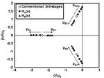
Both effects increase when the dominant pole pair (in the LHP) moves closer to the imaginary axis.
For a second order system there are formulas describing peaking (frequency domain) as well as overshoot (time domain) as a function of
the pole Q (which directly is related to the pole position).
These formulas can be found, for example, in
Sergio Franco: Design with operational amplifiers and analog int. circuits (Mc Graw Hill).
 

I know that in a 2nd order system, there is a standard description about Q or damping ratio. How about higher order?

Recently, I have desgned a cascade AMP which is used in the open-loop condition. In the bode diagram, the plot(Mag V.S. Freq) is flat without peaking, while in the trans digram, the overshoot(ring) is series. Do you know how I can solve this problem?

Thank you so much~~
 

I know that in a 2nd order system, there is a standard description about Q or damping ratio. How about higher order?

Recently, I have desgned a cascade AMP which is used in the open-loop condition. In the bode diagram, the plot(Mag V.S. Freq) is flat without peaking, while in the trans digram, the overshoot(ring) is series. Do you know how I can solve this problem?
Thank you so much~~

When you see an overshoot there must be a feedback loop.
Since you operate the cascade in an open-loop configuration this loop must be a local (or a hidden, unwanted) feedback loop (exhibiting a small phase margin).
What is the operating frequency?
It would be best to show us the complete circuitry.

ampcore.png

Thanks a lot, in fact my ckt does have a feedback as shown in the pic.

Assuming that, every G(s) has the form of A/(1+sRC), and Gf(s)=B/(1+sRC);
Due to the interleaving feed back, the six poles,2 real and 2 pair of complex, are splitting.
splitting.png

I see that one pair of the complex pole will have a higer reactive part , so is this the reason for the overshoot?
 

Hi Henry,

I am not able to evaluate your 2nd diagram and to deduce some ways from it to solve your problem - however, the block diagram contains three loops, each with 3 first order blocks. Thus, it is no surprise that the phase margin for at least one of these loops is small enough (depending on the dc gain values A and B) to cause some overshoot resp. ringing in the step response.
I suggest to check the loop gain for each local loop separately and to determine the corresponding phase margins.
 
I know that in a 2nd order system, there is a standard description about Q or damping ratio. How about higher order?

Recently, I have desgned a cascade AMP which is used in the open-loop condition. In the bode diagram, the plot(Mag V.S. Freq) is flat without peaking, while in the trans digram, the overshoot(ring) is series. Do you know how I can solve this problem?

Thank you so much~~

certain types of systems (very simple ones) can be characterized by a Bode plot. However, a stable looking Bode plot does NOT guarantee system stability. To do that you need to look at a root locus or Nichols plot.
 

When looking at the multiple loop system diagram, asking about possible overshoot sounds like a rather arbitrary question. I would ask for the underlying design objective in a first place. Secondly, how you are achieving stability at all.
 

Thank you!

And I remember that you have ever said "When we see a overshoot there must be a feedback", I do not fully undertand this. I think that if there is complex poles there may be overshoot. Could you please explain it in detail.

---------- Post added at 21:43 ---------- Previous post was at 21:39 ----------

I'm sorry, I am not sure I catch your idea.
 

Thank you!

And I remember that you have ever said "When we see a overshoot there must be a feedback", I do not fully undertand this. I think that if there is complex poles there may be overshoot. Could you please explain it in detail
.

Yes, you are right - overshoot in the time domain is an indication of complex poles in the s-plane.
This can be realized with L-C circuits (passive resonance) or with active R-C circuits and feedback. R-C circuits without feedback do not possess complex poles.
 

Status
Not open for further replies.

Part and Inventory Search

Welcome to EDABoard.com

Sponsor

Back
Top