Welcome to our site! EDAboard.com is an international Electronics Discussion Forum focused on EDA software, circuits, schematics, books, theory, papers, asic, pld, 8051, DSP, Network, RF, Analog Design, PCB, Service Manuals... and a whole lot more! To participate you need to register. Registration is free. Click here to register now.
Perhaps it can be called a rudimentary op amp. I can't say what is its overall performance.
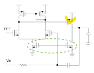
The leftmost section is a differential amplifier.
The right half creates a simple output stage. The feedback loop consists of a series capacitor.
I imagine your question about biasing applies to the Nmos pair which I circled below? I find other schematics attaching additional circuitry to that bias wire. Right now it appears to have an undefined volt level.
It's called basic two stage OP in literature. As stated by Brad, biasing of the green encircled current source transistors has been omitted in the schematic.
This site uses cookies to help personalise content, tailor your experience and to keep you logged in if you register.
By continuing to use this site, you are consenting to our use of cookies.