Continue to Site

Welcome to EDAboard.com

Welcome to our site! EDAboard.com is an international Electronics Discussion Forum focused on EDA software, circuits, schematics, books, theory, papers, asic, pld, 8051, DSP, Network, RF, Analog Design, PCB, Service Manuals... and a whole lot more! To participate you need to register. Registration is free. Click here to register now.

normally open switch ttl & rs232 voltage level

Status
Not open for further replies.

PRASAN DUTT RAJU

Junior Member level 1
Joined
Jun 14, 2012
Messages
18
Helped
0
Reputation
0
Reaction score
0
Trophy points
1,281
Activity points
1,410
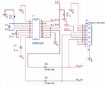
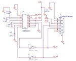
I,m designing USB to RS232 converter. For RS232 voltage level conversion I'm using two separate methods, one by using IC & other by using transistor converter circuit. But at the output as shown in the figure I need only one line Normally open switch as shown in the figure. The RS232 port should get the voltage from TTL without any interfere but when it gets some voltage from IC used here it should be closed.
rs232.jpg

What circuitry should I use in place of Normally open switch & will there be any problem of loading if switch is closed?
 

Since costing of the project is also a concern for me I was thinking of simply implementing a diode in place of the NO switch.
deg.jpg
Will it be a solution?
 

A diode drops 0.6 V. This may result in a high output not being recognized as a binary 1 by the receiving devices. It would be worth doing a few tests.

I guess pin 13 is an output. The diode will block current from flowing into pin 13. Therefore you are okay when pin 13 is low.

However is there a chance pin 13 could be high when another output is low? That is why it is risky to permit output pins to be connected.

Some devices have tri-state outputs because it is better to have high-impedance so that it prevents current flow either in or out. Have you determined if your device has tri-state outputs?
 

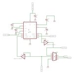
Thanks for your suggestion. I also think that Tri-state is a good solution to my design. I have connected the incoming signal to both the controlling pin & input pin so that when it detects an input signal then it will allow it to paas through it. My design should now look like this:Modified.jpg
Should it work now?
 

I can make out your schematic although the image remains low-res even when downloaded and zoomed in.

It looks as though you installed buffer IC's. They are powered up by a high incoming signal. This transmits the high signal to the output.

It's a clever idea and it might work if there is sufficient current coming down the line, to power the buffer. (The IC will be connected to the ground supply rail.)

Another factor... the question whether the output level really will be high enough to be close to the level of the incoming positive. If it is not then you're back to the same concept of putting a diode inline. Did you test whether an inline diode pulls the signal down too low, such that it is no longer detected as a 'high'?
 

(The IC will be connected to the ground supply rail.)

Another factor... the question whether the output level really will be high enough to be close to the level of the incoming positive. If it is not then you're back to the same concept of putting a diode inline. Did you test whether an inline diode pulls the signal down too low, such that it is no longer detected as a 'high'?

As per I know there very low dissipation through buffer so it should work. However I've not got hardware components at hand so I've not checked it yet.
What does it mean "The IC will be connected to ground supply rail"?
 
Last edited:

What does it mean "The IC will be connected to ground supply rail"?

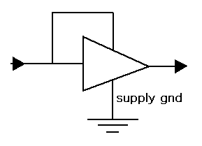
Simulators do not always show a logic gate having positive and negative supply going to it.

This is the connection that is implied:

2383226700_1350241099.gif
 
I've got that. In order to solve the error I've connected a global source in the schematic named VCC & it was solved.
 
Last edited:

Status
Not open for further replies.

Similar threads

Part and Inventory Search

Welcome to EDABoard.com

Sponsor

Back
Top