Continue to Site

Welcome to EDAboard.com

Welcome to our site! EDAboard.com is an international Electronics Discussion Forum focused on EDA software, circuits, schematics, books, theory, papers, asic, pld, 8051, DSP, Network, RF, Analog Design, PCB, Service Manuals... and a whole lot more! To participate you need to register. Registration is free. Click here to register now.

Non-ideal R L and C

Status
Not open for further replies.

engr_joni_ee

Advanced Member level 3
Joined
Nov 3, 2018
Messages
750
Helped
2
Reputation
4
Reaction score
4
Trophy points
18
Activity points
6,232
Hi,

The impedance of a capacitor decrease with frequency.
The impedance of a inductor increase with frequency.

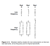
How the capacitance and inductance changes with frequency ?

At which frequency when designing PCB layout the SMD packages of R L and C have significant changes ?
 

Attachments

  • Untitled 195.png
    Untitled 195.png
    38.9 KB · Views: 95

Hi,

there is no general answer, every part reacts differently. Thus in those cases
I check the datasheet and other informations provided by the manufacturer.

Klaus
 

But is that true that Resistance, Inductance and Capacitance are function of frequency ? The impedance of Capacitor and impedance of Inductor are function of frequency.
 

Hi,

indeed I did not yet care.

Fact is, that the impedance of a capacitor does not follow the the rule of an ideal capcitor, because of the series R (ESR) in first place. But there still are other effects, like series L, speed of electrical signal, skin effect, proximity effect, piezoelecric effect ...

Since at higher frequencies the impedance is higher than of an ideal capacitor, it looks like it has less capacitance.

(So for me unitl now it was not of interest if the impedance becomes higher because of ESR or because of "smaller" capacitance. For me the information is important if I can use it to modify the behaviour. I can not modify the behaviour of a capacitor, but I can modify the PCB layout. With usually a much higher effect).
I guess that on a winding capacitor with its lengthy electrodes the speed of signal may have an influence of the "effective capacitor area", thus on very high frequency here indeed the capacitance may be reduced.

So in detail it depends. On the part, wiring and the frequency range of interest..

Klaus
 

Perhaps circuit behavior does influence a component such that its value changes temporarily. I've made real-life LC oscillators whose resonant frequency is based on a standard formula. The formula contains no variable representing ohmic R, nor Amperes nor Volts.

So the oscillating frequency doesn't change, or it's not supposed to.

Nevertheless when I increase the voltage I've watched the frequency change slightly, by a few percent. (I forget whether it speeds up or slows.)

It's hard to be sure which influences what. Suppose we wish to drive it at various frequencies. How will we know what reading to take, to discover where is the influence specifically on L & C values? Possibly output amplitude....
 

Status
Not open for further replies.

Part and Inventory Search

Welcome to EDABoard.com

Sponsor

Back
Top