Continue to Site

Welcome to EDAboard.com

Welcome to our site! EDAboard.com is an international Electronics Discussion Forum focused on EDA software, circuits, schematics, books, theory, papers, asic, pld, 8051, DSP, Network, RF, Analog Design, PCB, Service Manuals... and a whole lot more! To participate you need to register. Registration is free. Click here to register now.

noise injection in opamp

Status
Not open for further replies.

weeb0

Junior Member level 2
Joined
Jan 26, 2008
Messages
21
Helped
0
Reputation
0
Reaction score
0
Trophy points
1,281
Activity points
1,472
Hello,

I did not designed analog circuit for long time (I was more on digital and firmware side).

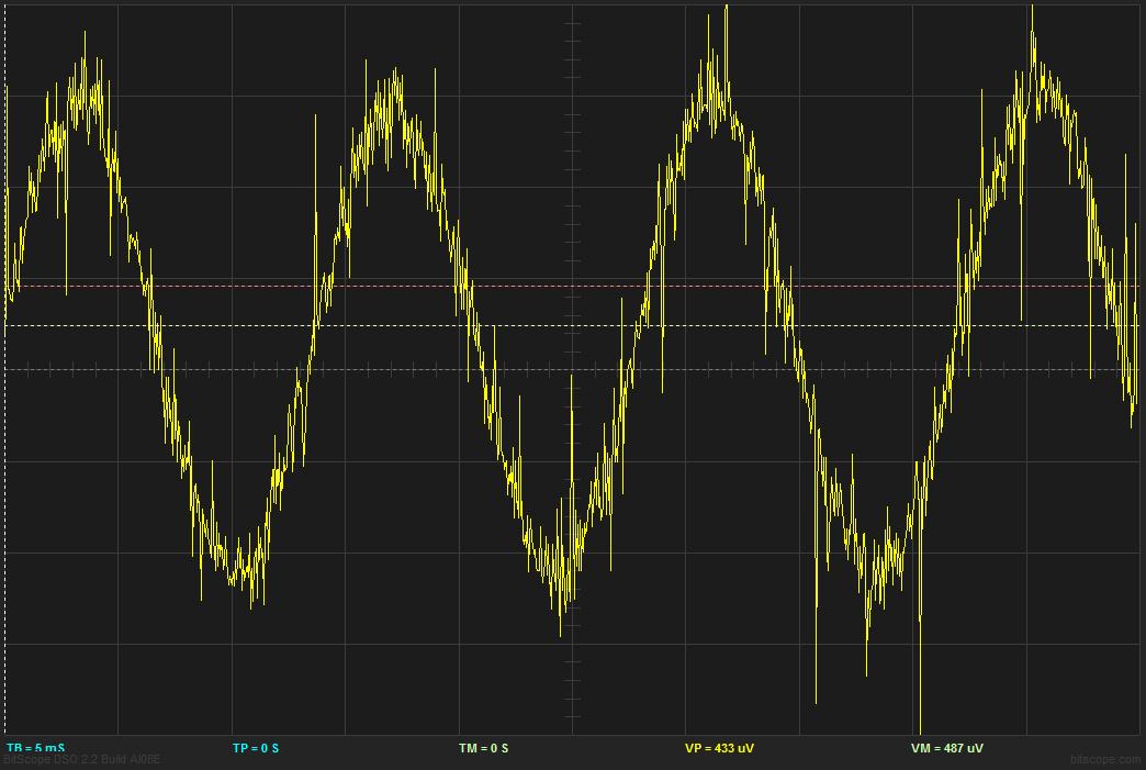
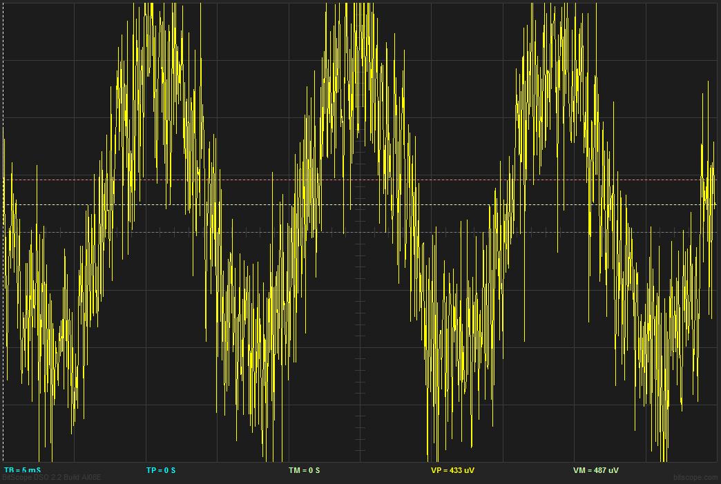
But now, I have to work on a project which require +-1mV sinusoidal (low frequency, 200Hz or less) signal then I have to do some other steps, but the problem is seen at the first stage.

first, I have an oscillator which provide me 2-3V, the signal is not very nice, but I think it is usable. (use the PT78NR105V and PT78ST105V)

I use the following steps :

Oscillator ---> resistor voltage divider ( 10Mohm with 10Kohm ) ---> opamp inverter buffer ( I use 10K as Rinput and 10K as Rfeedback (I have added a Cf of 18pF)

I use the first opamp to isolate the voltage divider.

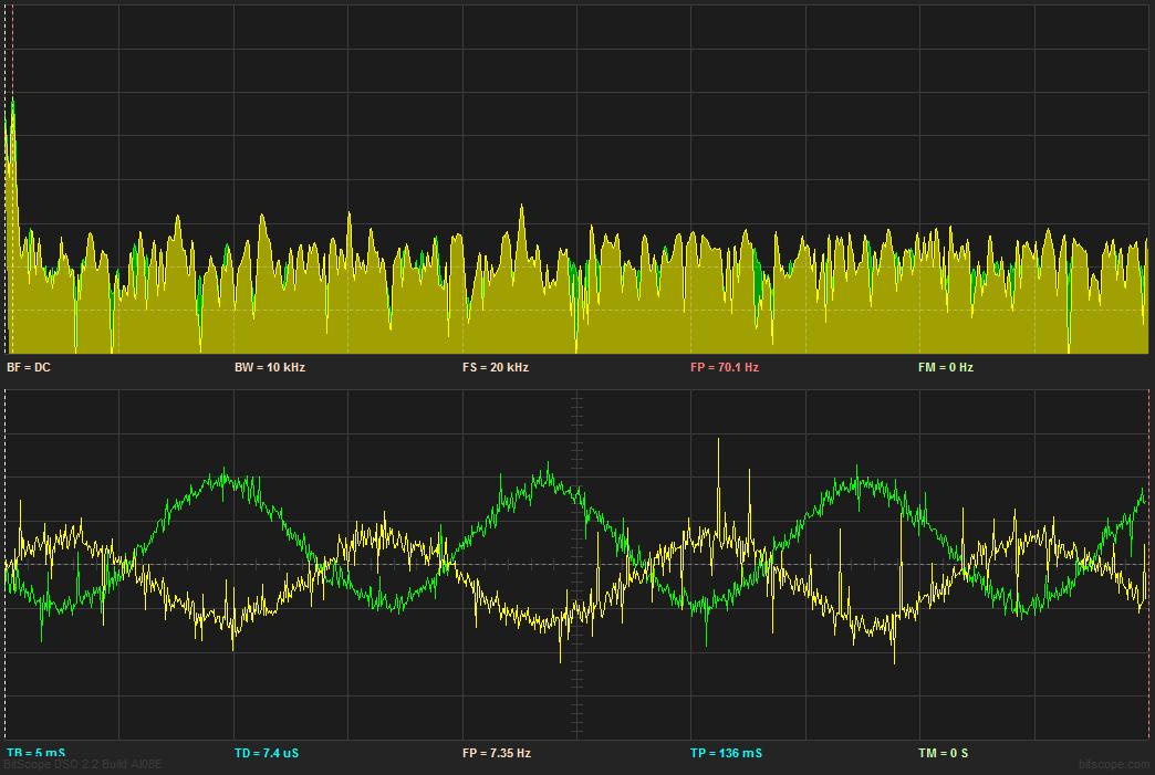
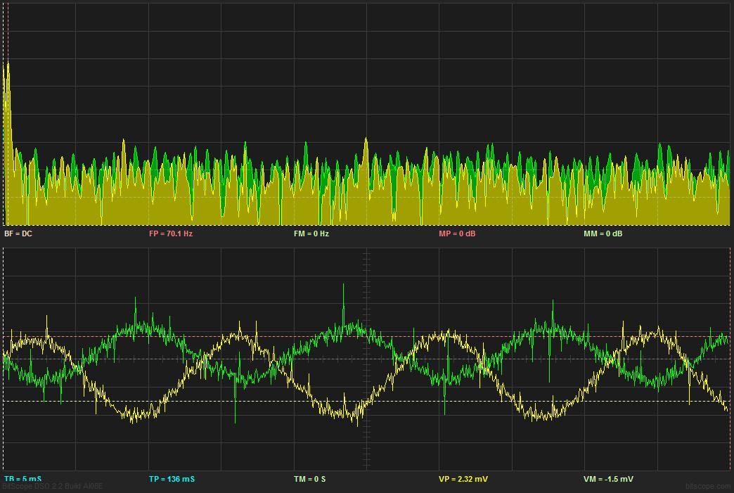
I can see the signal, but the output is very noisy. The opamp is driven at +-5V. The power noise is near 5mV. The opamp I use is the OPA228 8 soic (no trim). I've seen that the opa228 is not stable on low gain (<5) but tried the LT1197 (edit: LT1097) and I get similar results.

I tried to simulate the circuit with TINA everything is fine.

I know the Zinput is very high, but I never experienced anything like this. I tried to play with the CF, with the resistor value added RC filter ... I can see little change, but not a clean signal as I can see at the input.

I work on a PCB.

I don't know where to look at. I will try with other opamp, which are rated for lower frequency.

Is there anybody that could give me some clues to understand how to work with low voltage signals ?! Should I reduce my power noise ? Is there any paramter I should look?

I'm open to any advice !

Thank you a lot!
 
Last edited:

Please try more stages of filter for noise reduction. Sometime LC filter is better than RC filter.
 

Thank you for your comment.

In your experience, is my supply is suitable ? I mean, does 5mV of noise on my supply is acceptable for my application ?

I will try the LC filter. Thank you.
 

I think 5mV noise is acceptable for most of electronics systems.
However, this answer depends on your application.
For some sensitive circuits, you should reduce it further.
 

You can calculate the acceptable power supply interferences based on data sheet specifications of power supply rejection.

Some additional comments regarding your specific application described in post #1:
- LT1197 doesn't seem to be an existing device
- 10k divider impedance seems unreasonable high for low noise
- I wonder, why you don't implement a simple passive 1000:1 divider instead of an active outout stage. Output impedance can be as low as 1 ohm with standard OPs.
 
Thank you for your reply,

You are right, the component is not LT1197 but LT1097. I will correct the first post.

Why the noise (edit 10k) would be high for low noise ? can you elaborate a little bit more please? Is it because the current will be very low so?

I use a voltage divider (9.99Mohm with a 10Kohm -> 1000:1) then I only want to buffer the value to send it to another opamp (adder) to offset the signal.

I'm wondering if the noise is not caused by the opamp instability... (I will try low ESL/ESR capacitor (4 leads))

Regarding the PSRR, in the datasheet, I see the PSRR is between 114dB and 130dB. If I do understand well, 5mV * 10^{\Frac{-114}{60}} = 11.19nV so, if the noise is at 5mV the output will only be impacted of 11nV ? Did I use the right formula?

Thank you so much for your help!

note: I tried to use the latex function of the website, but I was not able to make it working .
 
Last edited:

The about 120 dB PSRR is valid for frequencies below 1 Hz, at 10 kHz, it's less than 40 dB. But the description "very noisy" signal is too vague for any conclusions of an interference source.
 
Thanks FvM.

I will post some waves this evening to show you what I mean by very noisy.

Regarding what you have said :

- 10k divider impedance seems unreasonable high for low noise

what do you mean ? I should try to reduce the resistor ? Which value would be acceptable and why ? Is it because the current will be very low ?

Thank you very much!
 

Reducing the resistor values implies:
- less sensitivity to capacitively injected interferences
- reducing the effect of OP noise currents (should be already O.K. with 10 k for LT1097)

Finally, you have the option of saving the buffer amplifier, by using the divider output directly. An output impedance of 1 to 10 ohm should be suitable in most cases.
 
Thank you FvM for your quick reply. I will try that this evening.

Thank you a lot.

I wanted to buffer the voltage divider because the signal goes into 4 opamp.
 

I wanted to buffer the voltage divider because the signal goes into 4 opamp.
Yes, but I don't think that this necessarily requires buffering. A variable load impedance or other signals, that may cause crosstalk can be reasons to impülement buffering though.
 
I changed the opamp for an OP97FSZ I think the signal is better, but not much. So, now I am convinced that the problem is not the opamp itself.

You can see the waveforms below.

both are :
1mV/div
5ms/div

Left is op amp input, right is op amp output. I changed the voltage divider (I use 1K with 1ohm I know, it is not 1000:1 but it is what I have on hand!)


here you can see the original 9.99Mohm W 10Kohm divider (1mV/div & 5ms/div) I don't understand why the signal has not the same voltage between the 1kohm/1ohm and the 9.99Mohm and the 10kohm.

05 - divider 9M99vs10k op97 input.JPG

With my scope integrated spectral analyser, I can see a nice peak at my frequency, but the noise floor is high.

Thank you for your comments :)!

edit : here is the output which I added an RC filter at the output ( 0.1uF / 10Kohm )
06 - output 9M op97 out rc 10k-0u1f.JPG
 
Last edited:

I observe the "noise" have a period of about 15mS. The frequency will be about 67Hz.
Is there any signal with this frequency in your system?
 

The 70Hz is my signal. The noise is the high frequency on the signal. That is what I'm trying to fight.

Thank you!
 

Let's start with 1 ms low-pass filtered signal. The wide band noise is conisderable reduced, but you see short spikes, that can't have passed the filter. In other words, you see measurement artefacts, caused by an unsuitable setup, e.g. probe ground clips or common mode interferences. As a test, short the input signal. Then you see only the interfering signals.

Secondly. The comparison between OP input and output signal reveals, that a considerable part of the noise is regular OP noise. You have been previously talking about low frequency signals. The OP has at least several 100 kHz bandwidth and the oscilloscope much more. So you'll see a lot of noise voltage, which rises basically with squareroot of bandwidth. I suggest some calculations about expectable resistor and amplifier noise and intended signal to noise ratio. Signal filtering should be applied according to the results.

If the 1k divider has an unexpected low output voltage, check the input voltage. Possibly you have a source impedance, that causes a voltage drop.
 
Thanks a lot again for your reply!

Here is the scope floor noise. (1mV/div 5ms/div)
08 - bruit fond oscilloscope.JPG
You are right, the noise on both signal are measurement artefacts. (I use a low end bitscope (BITSCOPE = PC OSCILLOSCOPES AND ANALYZERS))

The OP I use has a 900KHz bandwidth. I'm not sure to understand how you can see voltage noise and what is regular op amp noise.

Here is the waveform with input/output. The green signal is input and the yellow one is output. The only load on the opamp is the rc filter and one serial 10k // 8pF (again 1mV/div & 5ms/div).
07 - out vs input rc op97.JPG
 

I have difficulties to relate the said input/output traces. At first sight, the signals seem to have different frequencies. At least, there's some low frequency component, that doesn't look like noise.
 

I'm sorry, I'm not working on this project, but will continue soon. I will post a new in vs out waveform. I have some problems understanding how the bitscope interface works...
 

OK, I'm back on the project, here is the output vs input. (green input, yellow output)

The opamp is unity gain, with an RC filter, the signal's output noise level is similar (seems to be my oscilloscope internal noise).


I did a small test, I switched the probe on the scope.(now the green is the output and yellow input)


I think the RC filter helped me to solve my opamp problem. But, I'm still questionning myself. I always have problems with opamps, They always introduce noise in my circuits, how can I achieve a nice circuit without needing any filter ? Is there my supply, the opamp I use...

Thank you.
 
Last edited:

One would need to refer to an exact circuit to analyse noise sources. In the shown waveforms, there are however signal contributions that are definitely not noise in a strict sense.

Although noise is sometimes used in a broad sense for any kind of interferences (of possibly unknown origin), the term should be narrowed to inherent resistor and semiconductor noise and uncorrelated signal contributions of similar nature. In the waveforms, there's surely a considerable amount of most likely amplifier born noise, but the strongest voltage peaks are either signal correlated, most obvious in the lower green trace, or pulse-like events, most likely electrical interferences picked up from the vicinity.

The signal correlated peaks may show OP non-linearities, particularly output stage crossover distortions. Or crosstalk from a signal generator trigger output revealing inappropriate wiring of the measurement setup.
 

Status
Not open for further replies.

Similar threads

Part and Inventory Search

Welcome to EDABoard.com

Sponsor

Back
Top