ljcox
Full Member level 5
- Joined
- Feb 1, 2006
- Messages
- 252
- Helped
- 25
- Reputation
- 50
- Reaction score
- 23
- Trophy points
- 1,298
- Location
- Melbourne Australia
- Activity points
- 3,110
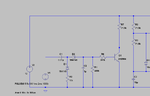
Does your parts supplier sell a cheap audio amp IC?The speaker output seems okay, but if I want to boost it, would I use a transistor? I have three to choose from: 2N2222, 2N3904 and 2N4401. Is there a difference?
It depends on how much output power you want and the tone quality. You could make a simple amp with 2 transistors, but the quality may not be adequate. See below.
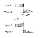
And, if I want the second note to fade out instead of stopping abruptly, is that difficult to add in?
It should not be too dificult. I'll put some thought into it.
For an example, see the one at the JayCar site **broken link removed**
Search for ZL-3600 and download the data sheet.
They have a mail order outlet in the US and their web site has a Canadian option which gives you the price in $CAD.
")