Continue to Site

Welcome to EDAboard.com

Welcome to our site! EDAboard.com is an international Electronics Discussion Forum focused on EDA software, circuits, schematics, books, theory, papers, asic, pld, 8051, DSP, Network, RF, Analog Design, PCB, Service Manuals... and a whole lot more! To participate you need to register. Registration is free. Click here to register now.

Need a charging circuit for 12V 7.2Ah Amaron Quanta Lead acid Battery

Status
Not open for further replies.
Hello cmsrlabs,

the problem of the of the lifetime of batteries is, that some batteries have a short life and the other one have a long life.

According to law of Germany the dealer or distributor of devices has to give 2 years warranty and to change the bad device without paying. After two years and one day the customer has to pay all. I don't know how it is in your country.

Normaly you can say, if their is no overload or other faults in the circuits all devices will survive the time of warrenty.

I develope and sell electronic devices and until now I have no problems with the warranty since 30 years.

Regards

Rainer
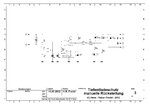
 

thanks for your reply.

Please explain page no. 3 of circuit to protect the battery from self discharge.

Also above circuit draws power from battery itself or from AC mains?
 

Hello cmsrlabs,

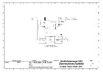
the circuit on page no.3 is not for protect the battery from self discharge but for protection for deep discharge.

This circuit is powered by the battery and controlled the voltage.

Tiefentladeschutz.JPG

Here is the circuit description:

The circuit consist of a comparator with OP1 and the switching stage with T5 and the relay Rel4.
The reference voltage is made by R14 and D8. OP2 is a impedance converter to get low resistance at the output. The reference voltage is 2,5V.
The voltage divider R9, P2 and R10 will give the switching point of the comperator. If the battery voltage is higher then 10,9V the comperator output is high and the relay is on. After the voltage drop under 10,9V the comperator output change to low and the relay goes off.

To adjust the switching point, connect a voltage of 10,9V to Point 5 and 6. Push the button shortly between point 9 and 10. If the relay switch on, turn P2 until the relay goes off, then a little bit back. push the button again. The relay must switch on and hold. Now reduce the voltage between 5 and 6 to 10,8V. The relay must switch off.

Now the circuit is adjusted. After charging the battery push the button to switch on the relay.

I hope the description is clear, else contact me again.

Regards

Rainer.


PS: If you can not adjust the circuit, reduce R9 to 33kΩ.
 
Last edited:

Relay switching corresponds to 10.8 Volt is clear to me but if AC mains is present i want AC (converting into DC) goes to load and if AC not present then in that case circuit first check Voltage corresponds to 10.8 Volt. If voltage > 10.8 Volt, it switches the Relay else not.

I am planning to use two comparators with one Relay. One comparator is used to detect AC and another is used to detect 10.8 Volt.

1) When AC is present, switch Off the relay--> AC goes to load. This is through first comparator.
2) When AC is not present, it checks:
a) if Vbat>10.8 Volt , switch on the relay--> Vbat goes to load.
b) if Vbat<=10.8 V, switch off the relay--> In that case relay switch toward AC side, but as no AC is there. So at the output we get 0 volt and load gets off.

I tried to design circuit, but with success only in one case at a time.

I successfully completed above tasks with PIC but seems costly.

Any idea to solve above task with one relay.

- - - Updated - - -

@tpetar

How life of battery relates with Internal resistance of battery.

- - - Updated - - -

@rfredel

Attachment 80882 seems invalid link.
 

How life of battery relates with Internal resistance of battery.

You must read about battery construction and principe how battery working, the answer will appear by itself.

I have several car lead acid around 13 year old, of course not in car. Monitoring internal resistance of battery when its new, and later periodically.
 
Last edited:

Hello cmsrlabs,

the attached circuit is a circuit of a commercial emergency light system, what I have sell to some of my customers.

I only modify the charging circuit and the deep discharge protection for myself to build it. I do it two times for my houses here in Germany and in Phillipines.

The deep discharging protection only controll the battery, not the AC line. The AC line is controlled by relay Rel3. If AC power is lost, relay 3 change to battery power, if S1 is close and deep discharge protection is on. The battery will be under charge, as long as line power is present. So the battery will be fully charge every time.

If you want, that the emergency light is on every time, you don't need S1, Rel1 and Rel2.

You can save Rel3, if you use two high current diodes instead of the relay contacts. Additional you need also a bridge rectifier and a smoothing capacitor direct after the transformer. You must be shure, that the voltage after the rectifier is min. 1V higher then the battery voltage. I think this solution is not good, because you need heatsinks for the rectifier and the high current diodes.

I can try to help you in designing circuits, but I have no knowledge about PIC. I'm too old to learn this again. :lol:

In moment I try to understand the function of soundprossesors, because my main profession is to develop sound systems in customer requirements.

Regards

Rainer
 

Attachments

  • Übersicht Notlicht.JPG
    Übersicht Notlicht.JPG
    470.6 KB · Views: 98

Put one diode between charger and battery (+), to prevent discharging battery by charger when it is in off state. Include diode voltage in calc of charging voltage.
 

Here i am attaching my requirement.

a) When AC is present Comparator 1 detects it and feed the signal to relay so that relay gets off.

b) When AC is not there, and Vbat >10.8 comparator 2 detects it and feed the signal to Activate it. Once relay Activate, battery voltage goes to load.

c) When AC is not there, and Vbat <10.8 comparator 2 detects it and feed signal to make relay Off. In that cost load switch to AC side and as AC is not there, load get shut down.Charging.JPG

- - - Updated - - -

I tested your circuit with auto cut option using PIC.

When Vbat<10.8 Volt load gets cut off, but when i applied AC mains, it start charging at the rate of 400mA.

Above is right or should i increase the current upto 700mA.
 

And when i start charging from 8 Volts, charging current appears 700ma and after that current decreases
 

You kill battery! If you have 6 cells of lead acid, you kill battery for sure. 8V is too low voltage.

Charging 6 cells of lead acid should start from at least float charge voltage. Charging starting current and max charging current is in posted datasheets in earlier posts.
 
Last edited:
I tried this just to know the time taken to charge battery from low voltage (in rare case due to some reason if Vbat goes below 8 Volt).

- - - Updated - - -

I want to confirm whether i need to increase current from 400mA to 700mA at charging of 10.8 Volts
 

No need for that.

You just need at least float charge voltage with limited current to max 0,7A (700mA). You can have multistage charger with higher first stage charging voltage accordint to datasheet, but also with limited current to 0,7A.

Lead acid charging process should be voltage and current controlled.

- - - Updated - - -

Do you need some circuit ?

How you standing with uC (programming - putting firmware into uC) ?
 

Thanks for your reply.

As you said Lead Acid Battery Charging should be Voltage and Current Controller but above circuit posted by Rainer is only current controlled, voltage remains constant.

I am fine with programming of PIC. Please posted some circuit for multistage charging.

- - - Updated - - -

means i have to start charging at 700mA at float voltage of 10.8 Volt.
 

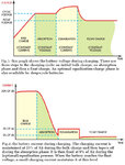
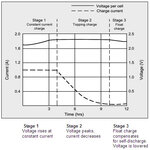
For better understanding charging stages :

Charging Stages.jpg

Lead Acid Charging Graph.jpg

- - - Updated - - -

You can search edaboard thread and solve your needs. You can find this existing thread, look mz post #7 :

https://www.edaboard.com/threads/252315/
 

that is the concept which i am searching for. thanks for you post.

if lead acid battery charging should follow 3 state charging, but i think circuit posted by Rainer also follows 3 state charging (initially current 700ma then decreases and then becomes zero.

What will be the benefit in terms of life of battery if we follow Battery Charger using PIC Micro,
 

Battery life according to datasheet is in range from 2-3 to 5 years. That is life range for good battery usage by datasheet rules.

Keep battery away from heat sources as transformer cores or some heatsink. If possible keep it at 25C-27C. Never keep battery discharged or partially discharged. Avoid usage of fast chargers.

Usage PIC or AVR, dont mean nothing. Bigger meaning have principe of functioning of charger and way how battery is charged.
 

so if we charge our battery with circuit stated by Rainer, then no need to go for AVR or PIC.

It also gives best results in terms of life??
 

First you should decide what you want to do, and next you should know how.

What you consider under "term of life" ?

I think you cycling with this.
 

Actually i want to maximize the life of battery with charging circuit.

If circuit posted by Rainer works well for Lead Acid Battery, then there is no need to go for Circuit with Micro controller. And if there is any drawback with this circuit then i will go for PIC.

If circuit by Rainer works well, then please help me in designing circuit which fulfills my requirement as per posted in post no.29
 

Status
Not open for further replies.

Part and Inventory Search

Welcome to EDABoard.com

Sponsor

Back
Top