Continue to Site

Welcome to EDAboard.com

Welcome to our site! EDAboard.com is an international Electronics Discussion Forum focused on EDA software, circuits, schematics, books, theory, papers, asic, pld, 8051, DSP, Network, RF, Analog Design, PCB, Service Manuals... and a whole lot more! To participate you need to register. Registration is free. Click here to register now.

Nanosecond pulse amplification

Status
Not open for further replies.
Joined
Mar 9, 2022
Messages
3
Helped
0
Reputation
0
Reaction score
0
Trophy points
1
Activity points
62
Hello Everyone!

I have an electrical pulse which I need to amplify for further use. The generated signal has around 1ns pulse width (signal looks similar to a Gaussian curve) and a peak of circa 2.2V (max. 40mA).
Attached is a overview of the circuit.
Summary of the overall circuit:
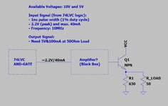
  • As supply voltages 10V and 5V are available
  • The Input Signal comes from a AND-Gate (74LVC2G8), with 2.2V (peak) and circa. 40mA. Signal repeats every 100ns (10MHz) and has a duty cycle of 1% (1ns pulse width).
  • The BlackBox should amplify the input signal to have 5V (peak) and 100mA at R_LOAD.
  • My understanding is that Q1 is for impedance matching.
  • Later R_LOAD will be replaced with a Laser diode
I have played around with some transistor configurations and wasn’t really successful, hoping now that someone can guide me in the right direction to amplified the input signal to 5V with 100mA at the output (to drive a laser diode). I was aiming for a transistor circuit with npn transistors like (which I have available):
Or should I use something different (like opamp, mosfet)?
I really appreciate any help from knowledgeable members,
Thanks you very much!

PS: I'm a bit lost after all the unsuccessful trials to get the signal amplified with a npn transistor circuit.
 

Attachments

  • amplifier_circuit.JPG
    amplifier_circuit.JPG
    53.1 KB · Views: 123


aren't all amplifiers made from "discrete" transistors? even if assembled on a substrate and looking like an ASIC ... (?)
 

Hi,

I've always seen "discrete" as the opposite to "integrated".
While a BFR590 is a discrete transistor, an ASIC uses "integrated" transistors.

Klaus
 

The amplifier can't be designed without an exact load specification (I/V characteristic of the laser diode). It's also very important to know the other laser diode parameters like threshold current respectively possible threshold range, maximum average and pulse current.

74LVC family seems a bit too slow to generate 1 ns pulses with reproducable width.
--- Updated ---

RF transistors are generally not well suited as saturated switches. The transistors should be kept forward biased in linear range over the switching cycle.
 
Hi,

isn´t this called a "hybrid"? .. because it uses discrete as well as integrated parts..

Klaus
 

CEL specializes in discrete transistors in Ghz area (for amps, NOT switches)


Regards, Dana.
 
Last edited:

Hello everyone,


Thank you for contributing to my thread. I was really hesitant to actually mention for what it is (pulsing a laser diode) because since I started this nanosecond pulse generator a very good IC implementation of this was thrown onto the market – which I intend to use for pulsing my laser.

Nonetheless I would like to try to get my 2.2V (40mA) signal amplified to drive a 50ohm load at 5V, this is merely to learn. What configuration should I use when we only think of the load as resistive, 50ohms, to get a 5V peak voltage from a available 2.2V pulse? Would it be possible to use the npn transistors like the BFR590, BFG106 and NSVF6003SB6 (because I have actually seen that…).

I might also change from the 74LVC logic to ECL, but for now it is more a learning experience and I would like to try to get the mentioned 5V at the resistive load of 50ohm.

Thanks
 

Last edited:

Hi Dana,
Thanks for the links. I don't think it is appropriate to think about any stray L and C when I'm not even able to amplify my signal at the moment in a simulationo_O

It seems that (from the link of the GlobalSpec forum) a "single emitter coupled pair" followed by a "simple emitter follower" should do the job to drive 50 ohms (for example with a BSX20/2N2969). I tried it now a few times, but I'm not able to get a sensible result...
Could someone please let me know how I would do the proposed emitter coupled pair (differential amplifier) with emitter follower?
Thank you
 

If it looks Gaussian to begin with then you are hosed. Your source, your instrumentation, your breadboard wireball in some combination are not showing you a "logic" pulse. No flat top, not logic. Logic missing all harmonics so you are at / past setup bandwidth.
 

Status
Not open for further replies.

Part and Inventory Search

Welcome to EDABoard.com

Sponsor

Back
Top