Continue to Site

Welcome to EDAboard.com

Welcome to our site! EDAboard.com is an international Electronics Discussion Forum focused on EDA software, circuits, schematics, books, theory, papers, asic, pld, 8051, DSP, Network, RF, Analog Design, PCB, Service Manuals... and a whole lot more! To participate you need to register. Registration is free. Click here to register now.

NAND simplification 4-1 multiplexor

Status
Not open for further replies.

jonnybgood

Full Member level 4
Joined
Dec 28, 2010
Messages
214
Helped
3
Reputation
6
Reaction score
1
Trophy points
1,298
Activity points
3,011
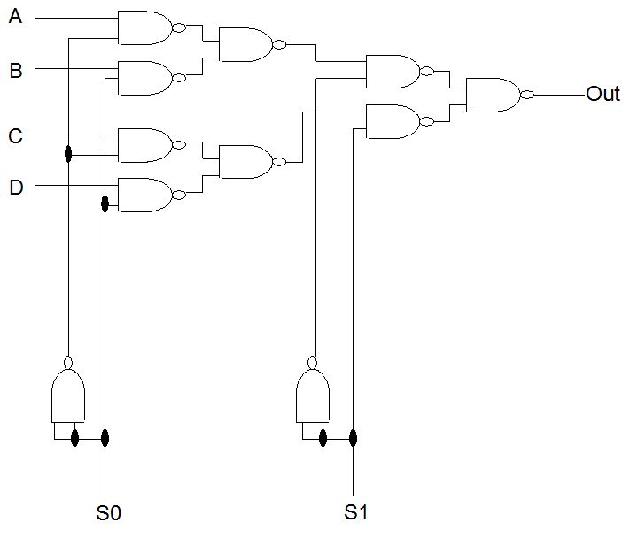
I've constructed a 4-1 multiplexor with and not and or gates, then i converted it to nand gates. I removed the extra not gates to simplify and was left with the circuit attached. Do you guys think it is simplified enough?

thanks

Brandon
 

Attachments

  • 4-1 multiplexor.bmp
    6.2 MB · Views: 146
  • multinandsimp.bmp
    126.3 KB · Views: 140

Hi,

I think this circuit is also a 4:1 mux (with only 11 NAND)


regards
 
Hi,
thanks for your help, it really does make sense and more efficient then my mux. Can I use De Morgan Laws to derive that simplified circuit or are there any other laws for NAND circuits?

thanks again Brandon
 

Can I use De Morgan Laws to derive that simplified circuit or are there any other laws for NAND circuits?

to be honest I do not know.

The circuit is a mux tree with 3 times 2:1 mux
every 2:1 mux can be build with 4 NAND
So we would have 3 time 4 NAND. (But we can share one NAND which is used as an inverter)
In the result we have 11 NANDs

From my experiance a tree architecture is often a effective solution

regards
 

I appreciate the idea of the tree architecture and i will look into it very deeply as i think i am going to present the two circuits: mine and the one you suggested and elaborate on the two.

thanks a lot for your help

Brandon
 

Hi,

I think this circuit is also a 4:1 mux (with only 11 NAND)


regards


I test in Quartus II. Result was wrong. Try to substitute your schematic circuit use truth table. You will see it.
 

I test in Quartus II. Result was wrong. Try to substitute your schematic circuit use truth table. You will see it.

The difference between the original (using INVERTORs, AND and OR gates) and the simplified circuit is only in possible hazards that are more likely to happen in the second (the simplified) one (due to more different delays of individual branches of the circuit).
The original circuit posted by trojsi is described as follows:

(1) 1_.PNG

factoring out /S1 from the first two terms and S1 from the following two yields (simplified expression, as to gate count):

(2) 2_.PNG

applying De Morgan we obtain:

(3) 3_.PNG

this expression describes exactly the circuit originally posted by qieda.

It means the circuits both implement the same logic function (and therefore have identical truth tables),
but the output signal of the simplified circuit "suffers" more from hazards (as I wrote above; this fact is not necessarily a bad thing, it depends on the intended use).

Note:
applying De Morgan right on the original expression (1) we obtain:

(4) 4_.PNG

so, if we don't insist on two-input NAND gates, the resulting circuit can be even simpler (gate count wise):

mpx4-1.png
 
Last edited:
Status
Not open for further replies.

Part and Inventory Search

Welcome to EDABoard.com

Sponsor

Back
Top